Outdoor All-Terrain Autonomous Navigation Robot with GPS-IMU Jaguar User Guide Copyright © 2010, Dr Robot Inc. All Rights Reserved. www.DrRobot.
Copyright Statement This manual or any portion of it may not be copied or duplicated without the expressed written consent of Dr Robot. All the software, firmware, hardware and product design accompanying with Dr Robot’s product are solely owned and copyrighted by Dr Robot. End users are authorized to use for personal research and educational use only.
Table of Contents I. II. III. IV. V.
I. Specifications Jaguar Mobile Robotic Platform is designed for indoor and outdoor operation. It comes with two articulated arms and is fully wirelessly (802.11G) connected. It integrates outdoor GPS, 6DOF IMU and digital compass for autonomous navigation. Jaguar platform is rugged, light weight (< 22Kg), compact, weather and water resistant. It is designed for extreme terrains and capable of climbing up stairs.
Motion and sensing controller (PWM, Position and Speed Control) 5Hz GPS, 6DOF IMU and digital compass Laser scanner (4m or 30m) (Optional) Temperature sensing & Voltage monitoring Headlights Color Camera (640x480, 15fps) with audio WiFi802.11G (Optional WiFi 802.11N) Ethernet Serial (RS232) Long range antenna (Optional) Ethernet General purpose communication and power port Game Pad Controller Head mounted display (Dual 640 x 480), equivalent to 60” display viewed in 2.
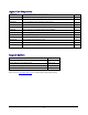
Jaguar Core Components JAGUAR-ME Jaguar Chassis (including motors and encoders) 1 PMS5005-J Motion and Sensing Controller (Jaguar Version) 1 WFS802G WiFi 802.11b/g Wireless Module 2 DMD2500 25A (peak 40A) Dual-channel DC Motor Driver Module 2 PMCHR12 DC-DC Power Board 1 AXCAM-A 640x480 Networked Color Camera (max. 30fps) with Two-Way Audio 1 OGPS501 Outdoor GPS Receiver with 5Hz Update Rate and WAAS 1 IMU9000 9 DOF IMU (Gyro/Accelerometer/Compass) 1 WRT802G 802.
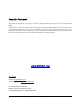
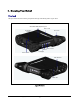
II. Knowing Your Robot Overlook The figure below illustrates the key components that you will identify on the Jaguar robot. GPS+6DOF IMU+Digital Compass Drive-Track Recharging Socket Arm-Track Laser Scanner Camera Headlights Power Switch WiFi Antenna Handle Bar Jaguar Platform Copyright © 2010, Dr Robot Inc. All Rights Reserved. www.DrRobot.
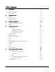
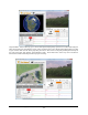
Operation Scenario Diagram below shows the typical operation scenario. The Jaguar is a wireless networked outdoor mobile robot. It comes with a wireless 802.11 AP/router. The remote host controller PC running the “Jaguar Control” program connects to the Jaguar robot via: Network cable – Connect the robot on-board AP/router.
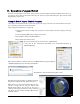
III. Operation of Jaguar Robot End user could develop his own Jaguar control program using the supplied development API and tools. Here, we are going to discuss how to control the robot using the included “Jaguar Control Program” (You need to install Google Earth program first). Using Dr Robot Jaguar Control Program This program will demonstrate how to control to navigate the Jaguar, move the arm-tracks and how to interpret, process, display and log multi-sensor information.
“FlyToSetPoint” button will bring you to the location (latitude/longitude) specified in outdoorrobotconfig.xml. This is the location you would like the map to center and show around. You should modify this location according to your location. This could be done by inputting the value in this xml file or navigating on Google Earth map to your interested point, then clicking “SaveSetPoint” button. The location value of the map center will then be saved to the outdoorrobotconfig.xml when program is closing.
You could use the vertical track bar to zoom in or out. When the GPS-IMU module is presented, this program will connect and display the GPS information on Google Earth and IMU raw data on the 6 chart boxes. When camera is presented, the video and Av control buttons will be show in the video window. You could use the included Game pad controller to navigate the robot.
then, click the “Set arm’s initial position” button to save this value and reset arm position display. Clicking button, you will display laser scanner data in polar view as shown below. Battery information and motor information will be displayed in window below: If the robot uses the included Li-Po battery, you need to stop the robot when voltage is below marked voltage (22.2V) to protect battery. Motor temperatures are also displayed in the display.
Recharging Jaguar robot uses high performance LiPo batteries. Extreme caution is needed when dealing with this type of battery, explosion and damage could occur. Please read the Charge Station manual first and follow all the safety rules before proceeding further. 1) Power on the Charge Station. Make sure "LiPo Charge" is displayed on the LCD screen. If not, use "Type/Stop" button to change it to "LiPo Battery". 2) Use "INC" button to choose how to charge battery.
IV. Hardware and Electronics Network Settings Wireless Router Setting The included pre-configured wireless 802.11 B/G router has the following pre-set settings: SSID DriJaguar Router LAN 192.168.0.245 WEP 128bits Login ID admin KEY 112233445566778899AABBCCDD Password drrobot Key Type Open Key Device Default Network Settings Note: The WiFi modules are configured for serial-to-Ethernet mode in Jaguar platform. WiFi Module 1 192.168.0.60 Port 1 Port Number 10001, UDP 115200.
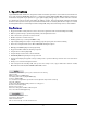
Charging Plug Antenna Right Driving Motor Left Driving Motor Right Arm Motor Left Arm Motor LiPo 22.2V 10AH OFF ON Main Switch Motor Driver Board #1 Power 5V 3.3V Camera (AV) Power 5V Copyright © 2010, Dr Robot Inc. All Rights Reserved. www.DrRobot.com - 15 - Wireless AP/Router GPS Module Antenna Power 5V Power 5V LAN 5V WiFi Module 2 6DOF IMU WiFi Module 1 Head Lights Power 3.3V Port 10002 Port 10001 DC-DC Power Board 5V Power 5V Power 3.
Motor Driver Board Two motor driver boards are used, one for the left and right track/wheel motors while the other one is for the arm-tack motors. Input power Max current Input voltage H-Bridge 2 channels up to 25A continuous power per channel, peak up to 50A per channel for a few seconds 6~24V, 30V absolute max Motion and Sensing Controller This is a special version of PMS5005 board.
Binary Output 9DOF IMU (Gyro, Accelerometer & Digital Compass) Input power Gyro Sensors 5V LY530ALH - 300º/s single-axis gyro LPR530ALH - 300º/s dual-axis gyro 3 Axis ADXL345 13bit resolution Max +/-16G 3 Axis HMC5843 magnetometer 50Hz Output all sensor raw data and processed data by on-board MCU through serial port Accelerometers Magnetic Compass Output Frequency Laser Scanner Two laser scanner options are available, one with measurement range of 0.02-4m, and other one is 0.1-30m.
Motor with Encoder Jaguar (with arms) Track-arm motors Rated voltage Rated current Rated speed Rated torque Encoder resolution DC motors with steel gearbox 24V < 2.1A 63 RPM 20 Kg.cm x 2 1083 counts per revolution Track-wheel motors (2 units) Rated voltage Rated current Rated speed Rated torque Encoder resolution * DC motors with steel gearbox 24V 2.1A 122 RPM 16 Kg.
V. Further Development & Programming The Jaguar Control program The Jaguar Control program is written with C# program with Visual Studio 2008 express under .Net 3.5 framework. You could download the development tools (Visual Studio 2008 express under .Net 3.5 framework) free from Microsoft. Please refer to the “Dr Robot Application Development Notes on C# Programming for Robot Control” for further information.
Motion Control/Sensing System: Jaguar comes with a special version of PMS5005 as its motion control and sensing board. It follows the Dr Robot WiRobotSDK protocol and user could control and access Jaguar by Dr Robot ActiveX control (DrRobotSentinelActivexControl.ocx) and WiRobot gateway program. Based on the protocol, you can develop your own program on any system. You could request protocol sample code from Dr Robot using C++/Java.
leftWheelMotor.encoderDir = myJaguar.GetEncoderDir4(); rightWheelMotor.encoderPos = myJaguar.GetEncoderPulse5(); rightWheelMotor.encodeSpeed = myJaguar.GetEncoderSpeed5(); rightWheelMotor.encoderDir = myJaguar.GetEncoderDir5(); //temperature sensor here RightArmMotorTemp = Trans2Temperature((double)myJaguar.GetCustomAD7()); leftArmMotorTemp = Trans2Temperature((double)myJaguar.GetCustomAD5()); leftWheelTemp = Trans2Temperature((double)myJaguar.
Laser Scanner Laser Ranger sensor (4m version, URG-04LX) is connected to WiFi module–1 port 2 after voltage level conversion. You could access the sensor data via TCP socket at port 10002 with IP 192.168.0.60. Default settings for the serial port are: 115200, 8, N, 1, no flow control, TCP, port number 10002 Date and communication protocol could be found in “URG-04LX commspec_eg.pdf”. GPS GPS sensor output interface is RS232 serial port, and connected to WiFi module-2 port 2 after voltage level conversion.
Advanced Development Please refer to document “GPS-IMU Sensor Module and Outdoor Autonomous Navigation Program” for detail on autonomous navigation programming using the Jaguar GPS and IMU system module. Support and sample codes are available for using OpenCV, LabVIEW and MATLAB. Please contact support@drrobot.com for further information. Copyright © 2010, Dr Robot Inc. All Rights Reserved. www.DrRobot.