DR® 6.25 TOW-BEHIND TRIMMER/MOWER SAFETY & OPERATING INSTRUCTIONS Serial No. Order No. Original Language DR Power Equipment Toll-free phone: 1-800-DR-OWNER (376-9637) Fax: 1-802-877-1213 Website: www.DRpower.com Read and understand this manual and all instructions before operating the DR 6.25 TOW-BEHIND TRIMMER/MOWER.
Table of Contents Chapter 1: General Safety Rules............................................................................................................................................................ 3 Chapter 2: Setting Up the DR 6.25 TOW-BEHIND TRIMMER/MOWER ............................................................................................ 6 Chapter 3: Operating the DR 6.25 TOW-BEHIND TRIMMER/MOWER ............................................................................................
Chapter 1: General Safety Rules Read this Safety & Operating Instructions manual before you use the DR 6.25 TOW-BEHIND TRIMMER/MOWER. Become familiar with the operation and service recommendations to ensure the best performance from your machine. If you have any questions or need assistance, please contact us at www.DRpower.com or call toll-free 1-800-DR-OWNER (376-9637) and one of our Technical Support Representatives will be happy to help you. Labels Your DR 6.
Safety for Children and Pets Tragic accidents can occur if the operator is not alert to the presence of children and pets. Children are often attracted to the machine and the trimming activity. Never assume that children will remain where you last saw them. Always follow these precautions: Keep children and pets out of the working area and under the watchful care of a responsible adult. Be alert and turn the machine off if children or pets enter the work area. Never allow children to operate the DR 6.
Operating the Trimmer/Mower Safely This is a high-powered machine, with moving parts operating with high energy at high speeds. You must operate the machine safely. Unsafe operation can create a number of hazards for you, as well as anyone else in the nearby area. Keep in mind that the operator or user is responsible for accidents or hazards occurring to other people, their property, and themselves.
Chapter 2: Setting Up the DR 6.25 TOW-BEHIND TRIMMER/MOWER It may be helpful to familiarize yourself with the controls and features of your DR 6.25 TOW-BEHIND TRIMMER/MOWER as shown in Figure 1 before beginning these procedures. If you have any questions at all, please feel free to contact us at www.DRpower.com. DR 6.
Specifications Engine Cutting Width Cutting Heights Cord Tip Speed (mph) Cord Size Offset Maximum Reach Frame Spindle Housing Spindle Shaft Drive Belt Drive Engagement Cord Line Plates Mow-Ball Wheels Machine Dimensions Machine Weight 625 Series Briggs and Stratton. See your Engine owner’s manual for detailed Engine Specifications 22" 2.7", 3.2", 3.7", 4.2", 4.7" 220 0.155" (Blue) or 0.175" (Green) POS #1: 29", POS #2: 40.
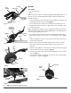
Hitch Assembly Assembly Tow Bar Label on Top Tools needed: Two 9/16" Wrenches Pliers 3/8-16 X 2.5" Flange Bolts and Locknuts Hitch Adjustment Brackets 1. Loosely assemble the Hitch Assembly to the Hitch Adjustment Brackets with two Flange Bolts and Locknuts by hand (Figure 4). 2. Loosely assemble the Tow Bar to the Hitch Adjustment Brackets with two Flange Bolts and Locknuts by hand. Tighten all four sets of hardware using two 9/16" Wrenches. Figure 4 3/8-16 X 2.
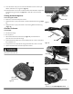
. Insert the Caster Yoke pivot into the Caster Bracket and secure with a 5/8" Washer and Cotter Pin using Pliers (Figure 9). 10. Install the Chain Link into the inside hole of the Caster Bracket and place the end of the Spring into the Link (Figure 10). Close the Link to secure the Spring. Greasing the machine before use Cotter Pin Caster Bracket Washer Tools and supplies needed: Grease Gun with General Purpose Grease 1.
Side Openings Center Opening Cord Installing the Cutting Cords There are two installation points on each Line Plate. Each point is 180 degrees apart. Always install two Cords, one opposite the other at the same height. If you buy Cutting Cord in rolls, cut it in 25" lengths. Cut them at an angle so they will be easier to install. Note: Soaking the Cutting Cords in water and trimming the ends at an angle will make installation easier. 1.
Adding Oil and Gasoline Note: Refer to the Engine Manufacturers Manual for more detailed Engine information. Tip: To avoid confusion, we recommend leaving the caps ON the Fuel and Oil Fills until you are ready to pour either gasoline or oil into the correct Fill. Note: You will need approximately 15 to 22 ounces of SAE 30 high detergent oil depending on Engine type. Use only SAE 30 high detergent oil classified “For Service SF, SG, SH, SJ” or higher. Do not use special additives.
Chapter 3: Operating the DR 6.25 TOW-BEHIND TRIMMER/MOWER This machine is designed to operate at full throttle for desired trimming quality. Never trim at a slower speed; doing so can cause stress to the drive system and could cause damage to the machine that is not covered under warranty. Read and understand your Tow Vehicle user’s manual and all safety Warnings for operating your Tow Vehicle safely before operating this DR 6.25 TOW-BEHIND TRIMMER/MOWER.
2. Install the two Bolts and Locknuts and tighten with two 9/16" Wrenches. Note: The Tow Hitch can be rotated to position the Clevis Pin holes at the top or bottom depending on how much adjustment you need to adjust the Tow Bar to level the machine. Swivel Frame Snap Safety Pin Adjusting the Tow Bar Offset The Tow Bar offset adjusts the trimming distance from the center of the Tow Vehicle. The straight in line position trimming distance is 29". The first offset position will trim a distance of 40.5".
Starting the Engine and Trimmer Head See Engine owner’s manual for more detailed starting information. Operator Zone When using the Trimmer, make sure you are standing in the safe operating area (OPERATOR ZONE) as shown in Figure 24. You must stay in the safe operating area at all times when starting or stopping the machine. The Trimmer Head is always spinning when the Engine is running. Stay away from the Trimmer Head area when the Engine is running or you could be injured by the spinning Cords.
Approach obstacles (Buildings, fence posts, Trees, Large Rocks etc) so the impact zone will be within the area of the Optimum Impact Zone Label (Figure 27). This will ensure the best spring action and trimming coverage around the obstacle. If you do run into debris and the Trimmer becomes tangled, Shut off the Tow Vehicle, set the parking brake and remove the Key.
Chapter 4: Maintaining the DR 6.25 TOW-BEHIND TRIMMER/MOWER Regular maintenance is the way to ensure the best performance and long life of your machine. Please refer to this manual for maintenance procedures. Shut off the Tow Vehicle, set the parking brake and remove the Key. Shut off the Trimmer Engine and after all moving parts to come to a complete stop, wait five minutes before performing any maintenance procedure or inspection on the Trimmer.
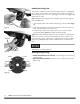
Replacing the Mow-Ball® or Line Plates Tools and Supplies Needed: Phillips head Screwdriver with at least a 6" shank Gloves 2. Align the hole in the Anti Wrap Canister with the hole in the internal housing at the location shown (Figure 30). Screwdriver 3. Insert a Philips Head Screwdriver into the hole in the Anti Wrap Canister and the hole in the internal Housing. 4. Rotate the Mow-Ball® Assembly until the Screw Driver slides into a hole in the shaft, locking it into place. Trimmer Cord 5.
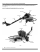
Replacing the Drive Belt Swivel Frame Tools needed: 3/8" Wrench Two 9/16" Wrenches Tow Bar 1. Set the Tow-Bar offset to the furthest offset position by removing the Snap Safety Pin and rotating the Tow Bar to the far right (Figure 32). Reinstall the Snap Safety Pin through the holes in the Tow Bar and Swivel frame. Snap Safety Pin 2. Lift the right side of the machine up and support it with a Jack stand (Figure 33). Figure 32 3. Remove the Trimmer Cord from the Head. 4.
Replacing the Tracking Wheel Tools Needed: Pliers Tracking Wheel 1. Remove the Cotter Pin with Pliers and remove the Tracking Wheel Assembly (Figure 37). 2. Install the new Tracking Wheel Assembly with the Valve Stem facing out. 3. Secure with the Cotter Pin. Replacing the Tracking Wheel Valve Stem Cotter Pin Figure 37 Tools Needed: Pliers 1. Remove the Cotter Pin with Pliers and remove the Caster Wheel Assembly (Figure 38). Caster Wheel 2. Install the new Wheel Assembly. 3.
Changing the Engine Oil Swivel Frame The Engine on your machine is not equipped with an Oil Drain Plug and will require some disassembly to fully drain the Oil. There is however, an Oil Suction Pump available to make removing the Oil easier. Please visit our web site at www.DRPower.com or call 1-800-DR-OWNER (376-9637) for assistance.
Storage It is quick and easy to partially disassemble the machine to take up less space when stored. Chain Link Tools Needed: 7/16" Wrench Spring 1. Loosen the Chain Link using a 7/16" Wrench and remove the Chain Link from the Frame (Figure 43). Inner Hole 2. Pull the Hair Pin from the Swivel Frame Shaft and remove the Swivel Frame from the Machine (Figure 44). Outer Hole Figure 43 Hair Pin Pivot Bracket Swivel Frame Figure 44 CONTACT US AT www.DRpower.
Chapter 5: Troubleshooting Most problems are easy to fix. Consult the Troubleshooting Table below for common problems and their solutions. If you continue to experience problems, contact us at www.DRpower.com or call toll-free 1-800-DR-OWNER (376-9637) for support. Shut off the Tow Vehicle, set the parking brake and remove the Key.
Troubleshooting Table (Continued) SYMPTOM The Engine lacks power or is not running smoothly. (Please refer to the Engine Owner’s Manual for Engine-specific procedures.) POSSIBLE CAUSE Check the Throttle Lever. The Throttle Lever should be in the fast (rabbit) position. Check for debris (hay seed, etc.) clogging the Air Filter Intake and clean out as required. The Engine’s Blower Housing, Throttle Linkage, and Cooling Fins should be free of debris.
Chapter 6: Parts Lists and Schematic Diagrams Parts List – Drive Assembly Note: Part numbers listed are available through DR Power Equipment.
Schematic – Drive Assembly 021114 CONTACT US AT www.DRpower.
Parts List – Frame and Tow-Bar Assembly Note: Part numbers listed are available through DR Power Equipment. Ref# Part# Description Ref# Part# Description 1 2 3 4 5 6 7 8 9 10 11 12 13 14 15 16 Frame, with Labels Label, DR Logo, 4.0", 4 Color Label, Safety Icons Label, Belt Routing Towbar, with Labels Label, Warning, Towbar Guard, Bumper, with Labels Label, Danger, Keep Back Label, Impact Zone Caster, Yoke Swivel Frame Bracket, Hitch Adjustment Hitch Assembly Wheel, 9 X 3.
Schematic – Frame and Tow-Bar Assembly 021114 CONTACT US AT www.DRpower.
Daily Checklist for the DR 6.25 TOW-BEHIND TRIMMER/MOWER To help maintain your DR 6.25 TOW-BEHIND TRIMMER/MOWER for optimum performance, we recommend you follow this checklist each time you use your machine. Shut off the Tow Vehicle, set the parking brake and remove the Key.