DR® ALL-TERRAIN FIELD and BRUSH MOWER™ Safety & Operating Instructions iii
And congratulations on your purchase of a new DR® ALL-TERRAIN™ FIELD and BRUSH MOWER! We have done our utmost to ensure that your DR® FIELD and BRUSH MOWER will be one of the most trouble-free and satisfying pieces of equipment you have ever owned. Please let us know of any questions or problems you may have. We want to answer or correct them as quickly as possible.
Safety Information We want you to enjoy years of productive use from your DR® FIELD and BRUSH MOWER. We don't want you to get injured, so please take a few moments to read the following guidelines for safely operating your new machine. Dress Appropriately · Wear safety glasses while mowing to protect your eyes from thrown objects. · Wear shoes with non-slip treads when using your DR® FIELD and BRUSH MOWER. If you have safety shoes, we recommend that you wear them.
· Keep combustible substances away from the engine when it is hot. · When operating over uneven terrain and slopes, use EXTREME CAUTION and make sure you're on firm footing at all times. · Mow only during the daylight hours. · Use extra caution when mowing in wet, slippery conditions. · ALWAYS OPERATE THE MOWER FROM BEHIND. Never pass or stand on the discharge (right) side or in front of machine when the engine is running.
Safety/Operation Labels Always replace damaged or missing safety and operation labels immediately.
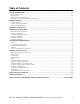
Table of Contents SAFETY INFORMATION...............................................................................................................................................iv DRESS APPROPRIATELY ...................................................................................................................................................iv PREPARATION ....................................................................................................................................................
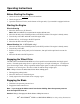
Before Starting Before you operate your DR®, please read these operating instructions and the engine manufacturer's owner's manual. Then, just ADD OIL and GAS, attach the battery wire and you're ready to go! Tools & Supplies Needed: · (2) 5/16 wrenches or sockets · SAE30 HD (High Detergent) oil · fresh unleaded gas Add Oil and Gas 1. Place the machine on a level surface and add SAE30 HD (High Detergent) oil to the reservoir. Check the dipstick frequently while filling to avoid overfilling.
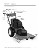
Controls & Features Note: Kawasaki Model shown.
Operating Instructions Before Starting the Engine 1. Check the oil level every time you use the machine. 2. Check the gas level. 3. Open the fuel shut-off valve (on the bottom of the gas tank), if your model is equipped with one. Starting the Engine Electric-Starting 1. Move the shift lever to N (Neutral). Note: Shift lever MUST be in neutral or the engine will not start. 2. 3. 4. 5. Move the throttle to the CHOKE position (to the RUN position if the engine is already warm).
Stopping the Blade Pull the blade control lever back to the DISENGAGED position. Note: Releasing the operator presence lever while the blade is engaged will cause the engine to shut off. Stopping the Engine 1. 2. 3. 4. 5. Disengage the blade. Move the shift lever to N (Neutral). Move the throttle control to IDLE. Turn the key to OFF and remove it for safety. Set the parking brake. If your machine is equipped with a fuel shut-off valve, close it when transporting or storing the mower.
Tips for Best Performance Slopes · We do not recommend using the DR® ALL-TERRAIN™ FIELD and BRUSH MOWER continuously on slopes greater than 25 degrees. Doing so could deprive the engine of oil and cause it to overheat. · To avoid freewheeling, shift into a lower gear before going down a slope. Do not shift while on a slope.
Cutting Brush & Saplings · When cutting woody material, small saplings, etc., allow the machine to ride up and over material slowly. Adjust your forward speed to varying conditions (Figure 5). · After cutting brush, etc., you may want to mow over it again to remove any remaining branches. It works best to mow from the trunk end toward the top as brush lies on the ground. Reverse · Be very careful of your footing when Figure 5 operating the machine in reverse. Know what's behind you and take your time.
General Maintenance *** For Engine Maintenance, Please Refer to the Engine Manufacturer's Owner's Manual. *** Regular Maintenance Check List Regular maintenance is the way to ensure the best performance and long life of your machine. Please refer to this manual and the engine manufacturer's owner's manual for maintenance procedures. Service intervals listed in the checklist below supercede those listed in the engine manufacturer's owner's manual.
Battery Care Electric-Starting Models Proper care can lengthen the life of a battery. Follow these recommendations to ensure your battery's best performance and long life: · Do not allow the battery charge to get too low. If the machine is not used, the battery should be charged every 4 – 6 weeks. · Store an unused battery in a dry area that does not freeze. · Do not charge an already charged battery.
Grease Fittings 1. There are two grease fittings below the black belt guard that need maintenance (Figure 6): · The belt idler arm should have 1-2 pumps of grease every 25 operating hours. · The mower spindle should have 3-4 pumps every 100 operating hours. Note: Over greasing will cause grease to leak out of the seals onto the mower drive belt. Unless instructed otherwise, pump only until you feel slight resistance (1-2 pumps). Figure 6 2.
Belts To Replace the Blade Belt ! WARNING: Always disconnect the spark plug wire before servicing your machine. 1. Remove the black belt guard by unscrewing the black knob, lifting the cover, and pulling up and back to remove it. 2. Release the belt tension lever (Figure 9). 3. Remove the belt from the pulley (Figure 10), then drop it from the engine pulley below the machine. To mount the belt, follow the above procedure in reverse.
4. Tilt the power unit back on the handlebars. 5. Remove the nuts on the clutch bracket and the clutch drive spring (Figure 12). 6. Remove the spring (Figure 13). Figure 12 Figure 13 7. Lift and swing the clutch bracket out of the way (Figure 13). 8. Remove the three belt guides (Figure 13). 9. Loosen the belt retainer bolts on the outside of the frame (one on each side) and slide the retainer back (Figure 14). 10. Remove the belt. To mount the new belt, reverse the above procedure.
To Remove/Replace the Blade Tools Needed: · 15/16" wrench or socket · air wrench if available · rag or gloves to handle the blade · 2 x 4 to brace blade ! WARNING: Always disconnect the spark plug wire before servicing your machine. 1. Block the blade with a piece of wood between the blade and the skid on the chute side of the deck (Figure 15). 2. Remove the blade lock nut (right-hand, regular thread) and washer.
To Remove/Replace the Drive Chain Tools & Supplies Needed: · 1/2" wrench or socket (chain cover) · 7/16" wrench or socket (chain cover) · flat-head screwdriver · pliers ! WARNING: Always disconnect the spark plug wire before servicing your machine. 1. Remove the chain cover (Figure 17). 2. Remove the master chain link (Figure18). First remove the lock clip (A) with a flathead screwdriver and pliers. You'll need to lift one side and rotate the clip to get it off the master link.
To Remove the Wheels Tools Needed: · 3/4" socket with extension ! WARNING: Always disconnect the spark plug wire before servicing your machine. 1. Block the machine so the wheel to be removed is off the ground. 2. Remove the three nuts and slide the wheel off. To Adjust the Parking Brake Figure 20 Tool Needed: · 1/2" open end wrench ! WARNING: Always disconnect the spark plug wire before servicing your machine. To adjust the parking brake, tighten or loosen the nut shown in Figure 21.
To Remove or Change the Deck ! WARNING: Always disconnect the spark plug wire before servicing your machine. 1. Remove the black belt guard by unscrewing the black knob, lifting the cover and pulling up and back to remove it. 2. Release the belt tension lever (Figure 22). 3. Remove the belt from the pulley (Figure 23). 4. Remove the pin and collar (Figure 24), then pull the power unit away from the deck.
End of Season & Storage ! WARNING: Always disconnect the spark plug wire before servicing your machine. Please refer to the engine manufacturer's owner's manual for engine-specific procedures. · Change the oil (and oil filter, if applicable). · Remove the spark plug and pour about 1 ounce of motor oil into the cylinder hole. Replace the plug and pull the recoil starter rope until you feel strong resistance. This will coat the piston and seat the valves to prevent moisture buildup.
Troubleshooting ! WARNING: Always disengage the blade, turn off the engine and disconnect the spark plug wire before servicing your machine. Please refer to the Engine Manufacturer's Owner's Manual for specific engine maintenance and troubleshooting information. Belts The belt frays or rolls over the pulley Þ A pulley groove may be nicked. Check the belt for wear and hard spots. File off any nicks on the pulley. Þ The belt may be stretched. Replace it.
Engine won't start (continued) Þ Check the wire connections—especially the ground connection, the large green wire coming from the battery, where it connects to the engine. Þ Check the wire connections to the solenoid. Disconnect the green battery ground wire first to avoid sparks. Check to be sure that all of the connections are clean and tight. Reconnect the battery ground wire. Þ Check the ground connection on the solenoid (10.5 HP ES, 12.5 HP) where it’s bolted to the frame.
Handlebar Assembly Note: The circled numbers match the first column of numbers on the parts list.
Parts List—Handlebar Assembly Ref# 1 2 3 4 5 6 7 8 9 Qty 1 4 1 1 6 1 4 1 1 10 11 12 1 1 1 13 14 15 2 1 1 16 2 17 3 18 19 20 21 22 23 24 25 1 1 2 1 1 1 2 1 26 27 28 1 1 4 Part# Description 150041 Battery Shelf 110761 Nut, Nylon Lock, 5/16" - 18 151221 Handlebar, Left Hand 151211 Handlebar, Right Hand 150091 Bolt, HCS, 5/16" – 18 x 1.
Power Unit Assembly Note: The circled numbers match the first column of numbers on the parts list.
Parts List—Power Unit Assembly Ref# Qty Part# Description 1 1 150261 Frame, Main 2 1 100831 Engine, 10.5HP, B&S, e/s 100861 Engine, 12.5HP, TEC, e/s 139091 Engine, 15.0HP, KAW, e/s 139081 Engine, 8.0HP, B&S, e/s 147011 Engine, 8.0HP, B&S, m/s 3 1 150411 Mount, Fuel Tank 4 1 150291 Fuel Tank Assembly 5 1 150011 Fuel Cap With Gauge 6 2 150531 Strap, 2.
Brush Deck Assembly Note: The circled numbers match the first column of numbers on the parts list.
Parts List—Brush Deck Assembly Ref# Qty Part# 1 1 150761 2 1 150911 3 1 151371 4 2 150891 5 1 151331 6 1 150901 7 1 150121 8 9 10 11 12 13 14 15 16 1 1 1 1 1 1 1 1 1 150871 150831 150711 150641 151141 100721 100481 101771 151271 17 1 150941 Description Brush Deck Spindle Support Spindle Bearing, Ball, .787" Bore Key, Parallel, Round Ends, 1/4" x 3/16" x 7/8" Shim, .750" ID, .875" OD, 1.0" L with .1875" Slot Pulley, V, 8.
Differential/Axle Assembly Note: The circled numbers match the first column of numbers on the parts list.
Parts List—Differential/Axle Assembly Ref# Qty Part# Description 1 1 150251 Differential, Limited Slip 2 2 150621 Wheel & Tire, 18" x 6.50" – 8", Terr, 5 Lug 3 151721 Wheel & Tire, 18" x 6.50" – 8", Turf, 5 Lug 4 1 150191 Chain, #40, 88 Pitches with Master Link 5 6 150441 Nut, Lug, 1/2" - 13 6 4 110761 Nut, Nylon Lock, 5/16" - 18 7 4 123211 Bolt, HCS, 5/16" – 18 x 3.
Notes 28 DR® ALL-TERRAIN™ FIELD and BRUSH MOWER Safety & Operating Instructions
Daily Checklist for the DR® FIELD and BRUSH MOWER 4 OIL: With the machine on a level surface, remove the oil fill cap and check the oil level. Fill the reservoir according to the dipstick with SAE30 HD motor oil. 4 GAS: Fill the gas tank with fresh, unleaded gasoline, making sure the gas valve on the bottom of the tank is open. Always close the gas valve when storing your machine. 4 ENGINE: It is very important to keep the engine clean.