
Service manual
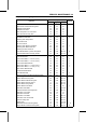
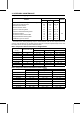
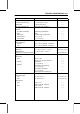

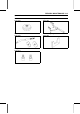
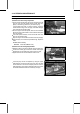
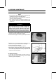
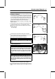
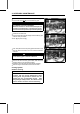
Table Of Contents
- tables
- LIST OF ABBREVIATIONS
- COUNTRY AND AREA CODES
- Units of Mass:
- Units of Volume:
- Units of Force:
- Units of Length:
- Units of Torque:
- Units of Pressure:
- Units of Speed:
- Units of Power:
- Basic Torque for General Fasteners of Engine Parts
- Basic Torque for General Fasteners of Frame Parts
- Throttle Lever Free Play
- Idle Speed
- Water and Coolant Mixture Ratio (when shipping)
- Valve Clearance (when cold)
- Valve Clearance (when cold)
- Belt Width
- Belt Deflection
- Spacers
- Actuator Lever Guide Shoe
- Engine Oil
- Tire Tread Depth
- Standard Tire
- Differential Control Lever Lock Position Length
- Front Final Gear Case Oil
- Rear Final Gear Case Oil
- Pad Lining Thickness
- Rear Brake Lever Free Play
- Brake Pedal Free Play
- Spark Plug Gap
- Brake Light Timing
- Terminal Names
- Sample Diagnosis Sheet
- Engine Doesn't Start, Starting Difficulty
- Poor Running at Low Speed
- Poor Running or No Power at High Speed:
- Connections:
- Throttle Sensor Input Voltage
- Input Voltage at Sensor
- Wiring Connection
- Throttle Sensor Output Voltage
- Idle Speed
- Output Voltage at Sensor
- Wiring Connection
- Throttle Sensor Resistance
- Inlet Air Pressure Sensor Input Voltage
- Input Voltage at ECU
- Inlet Air Pressure Sensor Output Voltage
- Inlet Air Pressure Sensor Output Voltage
- Inlet Air Temperature Sensor Output Voltage
- Output Voltage at ECU
- Inlet Air Temperature Sensor Resistance
- Water Temperature Sensor Output Voltage
- Speed Sensor Input Voltage
- Input Voltage at Sensor
- Speed Sensor Output Voltage
- Output Voltage at Sensor
- Vehicle-down Sensor Power Source Voltage
- Input Voltage at Sensor
- Vehicle-down Sensor Output Voltage
- Output Voltage at Sensor
- Ignition Coil Input Voltage at ECU
- Injector Power Source Voltage
- Power Source Voltage at Injector
- Injector Output Voltage
- Output Voltage at Injector
- Injector Wiring Inspection
- Injector Resistance
- Injector Fuel Line Maximum Pressure
- ECU Grounding Inspection
- ECU Power Source Inspection
- Fuel Pressure (Idling)
- Amount of Fuel Flow
- Pump Operating Voltage at Pump
- Operating Voltage at Pump Connector
- Engine Vacuum Synchronization Vacuum
- Throttle Sensor Output Voltage
- Connections:
- Standard Resistence:
- Radiator Cap Relief Pressure
- Thermostat Valve Opening Temperature
- Rocker Arm Inside Diameter
- Rocker Shaft Diameter
- Cam Height
- Camshaft Bearing Clearance ( 18)
- Camshaft Bearing Clearance ( 22)
- Camshaft Journal Diameter ( 18)
- Camshaft Journal Diameter ( 22)
- Cylinder Compression (Usable Range)
- Cylinder Head Warp
- Valve/Valve Guide Clearance (Wobble Method)
- Valve Seating Surface Outside Diameter
- Valve Seating Surface Width
- Special Tools - Valve Seat Cutters:
- Cylinder Inside Diameter
- Piston Diameter
- Piston/Cylinder Clearance
- Piston Ring/Groove Clearance
- Piston Ring Groove Width
- Piston Ring Thickness
- Piston Ring End Gap
- Actuator Lever Assembly Installation Length
- Measurement Length [E]
- Actuator Lever Assemblies
- Cover Bushing Inside Diameter [A]
- Sheave Bushing Inside Diameter [A]
- Spring Free Length [A]
- Shoe Side Clearance
- Drive Pulley Installation Length [A]
- Measurement Length [D]
- Drive Pulley Covers
- Sheave Bushing Inside Diameter
- Spring Free Length [A]
- Oil Pressure
- Connecting Rod Bend
- Connecting Rod Twist
- Connecting Rod Big End Side Clearance
- Connecting Rod Big End Bearing, Insert/Crankpin Clearance
- Crankpin Diameter
- Crankpin Diameter Marks
- Connecting Rod Big End Inside Diameter Marks
- Big End Bearing Insert Selection
- Crankshaft Runout
- Crankshaft Main Journal Diameter
- Crankcase Main Bearing Bore Diameter
- Shift Fork Ear Thickness
- Shifter Groove Width
- Toe-in of Front Wheels
- Maximum Tire Air Pressure (to seat beads when cold)
- Tire Air Pressure (when cold)
- Drive Bevel Gear Shims for Tooth Contact Adjustment
- Driven Bevel Gear Shims for Backlash Adjustment
- Output Bevel Gear Backlash
- Standard Length of Assembling:
- Standard Length of Assembling
- Front Final Gear Case Coupling Bushing Inside Diameter [B]
- LSD Clutch Torque (When variable differential control lever is r
- LSD Clutch Torque (When variable differential control lever is p
- 1. Pinion Gear Shims for Backlash Adjustment
- 2. Ring Gear Right Shims for Tooth Contact Adjustment
- 3. Ring Gear Left Shims for Tooth Contact Adjustment
- Front Final Bevel Gear Backlash
- Standard Length of Assembling:
- Standard Length of Assembling:
- 6. Pinion Gear Shims for Backlash Adjustment
- 7. Ring Gear Shims for Tooth Contact Adjustment
- 8. Ring Gear Shims for Tooth Contact Adjustment
- Rear Final Bevel Gear Backlash
- Recommended Disc Brake Fluid
- Disc Thickness
- Disc Runout
- Spring Action
- Spring Action
- Tie-rod Length
- Kawasaki-recommended chargers:
- Battery Terminal Voltage
- Terminal Voltage: 11.5 ∼ less than 12.8 V
- Terminal Voltage: less than 11.5 V
- Regulator/Rectifier Output Voltage
- Alternator Output Voltage
- Stator Coil Resistance @20°C (68°F)
- Regulator/Rectifier Resistance (Unit: kΩ)
- Ignition Coil Arcing Distance
- Ignition Coil Winding Resistance
- Ignition Coil Primary Peak Voltage
- Crankshaft Sensor Resistance
- Connections:
- Crankshaft Sensor Peak Voltage
- Ignition Timing
- Starter Motor Brush Length
- Testing Relay
- Radiator Fan Motor Lead Connections:
- Failure Indication Pattern and Failure Part
- Malfunction Mode
- Actuator Internal Resistance
- Actuator Internal Resistance
- Controller Power Supply Voltage
- Speed Sensor Output Voltage
- Controller Output Voltage (at 2WD/4WD Shift Switch OFF, 4WD)
- Controller Output Voltage (at 2WD/4WD Shift Switch ON, 2WD)
- Controller Output Voltage (to Actuators)
- Controller Output Voltage (to speed sensor)
- Controller Output Voltage (to 2WD/4WD shift switch)
- Controller Output Voltage (to engine brake actuator)
- Controller Output Voltage (to 2WD/4WD actuator)
- Forward/Reverse Detecting Sensor Resistance
- Fuel Level Sensor Resistance
- Water Temperature Sensor Resistance
- Testing Relay
- toc
- EMISSION CONTROL INFORMATION
- PLEASE DO NOT TAMPER WITH NOISE CONTROL SYSTEM (US MODEL only)
- Foreword
- General Information
- Before starting to perform an inspection service or carry out a
- Battery Ground
- Edges of Parts
- Solvent
- Cleaning Vehicle before Disassembly
- Arrangement and Cleaning of Removed Parts
- Storage of Removed Parts
- Inspection
- Replacement Parts
- Assembly Order
- Tightening Sequence
- Tightening Torque
- Force
- Gasket, O-ring
- Liquid Gasket, Locking Agent
- Press
- Ball Bearing and Needle Bearing
- Oil Seal, Grease Seal
- Circlips, Cotter Pins
- Lubrication
- Direction of Engine Rotation
- Electrical Wires
- Instrument
- KVF750D8F Left Side View
- KVF750D8F Right Side View
- Frame Number
- Engine Number
- Prefixes for Units:
- Units of Temperature
- Before starting to perform an inspection service or carry out a
- Periodic Maintenance
- The scheduled maintenance must be done in accordance with this c
- The following tables list the tightening torque for the major fa
- Oil Filter Wrench:
- Fuel System
- Throttle Lever Free Play Inspection
- Throttle Lever Free Play Adjustment
- Idle Speed Inspection
- Idle Speed Adjustment
- Air Cleaner Element Cleaning and Inspection
- Air Cleaner Draining
- Fuel Hose Inspection (fuel leak, damage, installation condition)
- Fuel Hose Replacement
- Cooling System
- Engine Top End
- Converter System
- Engine Lubrication System
- Wheels/Tires
- Final Drive
- Brakes
- Front Brake Pad Wear Inspection
- Front Brake Hoses and Connections Inspection
- Front Brake Hose Replacement
- Front Brake Fluid Level Inspection
- Front Brake Fluid Change
- Front Brake Master Cylinder Piston Assembly and Dust Cover Repla
- Front Brake Caliper Fluid Seal Replacement
- Front Brake Caliper Dust Seal and Friction Boot Replacement
- Rear Brake Plates Replacement
- Rear Brake Lever Free Play Inspection
- Rear Brake Pedal Free Play Inspection
- Rear Brake Lever and Pedal Free Play Adjustment
- Steering
- Electrical System
- Joint Boots Inspection
- General Lubrication
- Bolts and Nuts Tightening
- Fuel System (DFI)
- DFI System
- DFI System Wiring Diagram
- FI Indicator Light (LCD) [A]
- Vacuum Gauge Adapter:
- DFI Servicing Precautions
- Outline
- NOTE
- Self-diagnosis Outline
- Throttle Sensor Removal/Adjustment
- CAUTION
- Inlet Air Temperature Sensor Removal/Installation
- Water Temperature Sensor Removal/Installation
- Start the engine and switch the diagnosis mode to Dealer 1 mode
- Speed Sensor Removal
- Vehicle-down Sensor Removal
- Fuel Pump Relay Removal
- Ignition Coil ##1: Ignition Coil for Front Cylinder (Service Code
- Fuel Injector Removal
- Inspection Flow Chart
- CAUTION
- Fuel Pressure Inspection
- Fuel Pump Removal
- Throttle Lever Free Play Inspection
- Idle Speed Inspection
- ISC Valve Removal
- Air Cleaner Element Removal
- Fuel Tank Removal
- Cooling System
- Engine Top End
- Outside Circlip Pliers:
- Camshaft Chain Tensioner Removal
- Rocker Case Removal
- Camshaft Removal
- Cylinder Compression Measurement
- Valve Clearance Inspection
- Cylinder Removal
- This vehicle is equipped with a spark arrester approved for off-
- Converter System
- Engine Lubrication System
- Engine Removal/Installation
- Crankshaft/Transmission
- Outside Circlip Pliers:
- Crankcase Disassembly
- Crankshaft Removal
- Crankshaft Installation
- Connecting Rod Removal
- Connecting Rod Installation
- Crankshaft/Connecting Rod Cleaning
- Connecting Rod Bend Inspection
- Connecting Rod Twist Inspection
- Connecting Rod Big End Side Clearance Inspection
- Connecting Rod Big End Bearing/Crankpin Wear Inspection
- Crankshaft Runout Inspection
- Crankshaft Main Bearing/Journal Wear Inspection
- Shift Lever Removal
- Ball and Needle Bearing Replacement
- Wheels/Tires
- Final Drive
- Dummy Page
- Bearing Puller:
- Output Drive Bevel Gear Removal
- Special Tool -
- Output Drive Bevel Gear Installation
- Output Drive Bevel Gear Disassembly
- Output Drive Bevel Gear Assembly
- Output Driven Bevel Gear Removal
- Output Driven Bevel Gear Installation
- Output Driven Bevel Gear Disassembly
- Output Driven Bevel Gear Assembly
- Output Bevel Gears Adjustment
- Output Bevel Gear (Backlash-related Parts)
- Front Propeller Shaft Removal
- Front Axle Removal
- Front Final Gear Case Oil Level Inspection
- Torque -
- Front Final Gear Case Oil Change
- Variable Differential Control Lever Play Inspection
- Variable Differential Control Lever Play Adjustment
- Variable Differential Control Lever Removal
- Variable Differential Control Lever Installation
- Variable Differential Control Cable Installation
- Variable Differential Control Cable Lubrication
- Variable Differential Control Cable Inspection
- Front Final Gear Case Removal
- Front Final Gear Case Installation
- Front Final Gear Case Disassembly
- Front Final Gear Case Coupling Inspection
- Front Final Gear Case Assembly
- Oil Seal Installation
- Ring Gear Disassembly
- Ring Gear Assembly
- LSD Clutch Torque Inspection
- Pinion Gear Unit Disassembly
- Pinion Gear Unit Assembly
- Front Final Bevel Gear Adjustment
- Front Final Gear Case (Backlash-related Parts)
- Correct Tooth Contact Pattern: No adjustment is required.
- Incorrect Tooth Contact Patterns (Example 1)
- Incorrect Tooth Contact Patterns (Example 2)
- Rear Propeller Shaft Removal
- Rear Axle Removal
- Rear Final Gear Case Oil Level Inspection
- Torque -
- Rear Final Gear Case Oil Change
- Rear Final Gear Case Removal
- Rear Final Gear Case Installation
- Rear Final Gear Case Disassembly
- Rear Final Gear Case Right Cover Assembly
- Rear Final Gear Case Front Cover Assembly
- Rear Final Gear Case Assembly
- Rear Final Bevel Gear Adjustment
- Rear Final Gear Case (Backlash-related Parts)
- Ball or Needle Bearing Inspection
- Brakes
- Suspension
- Inside Circlip Pliers:
- Front Shock Absorber Preload Adjustment
- Front Suspension Arm Removal
- Steering
- Inside Circlip Pliers:
- Steering Stem Removal
- Steering Inspection
- Handlebar Removal
- Frame
- Seat Removal
- Front Carrier Removal
- Front Fender Removal
- Middle Cover Removal
- Front Guard Removal
- Left Footboard Removal
- Trailer Hitch Bracket Removal
- Electrical System
- Light/Dimmer Switch [A]
- Dummy Page
- Timing Light:
- There are a number of important precautions that should be taken
- Wiring Inspection
- Battery Removal
- Alternator Cover Removal
- Special Tool -
- Alternator Cover Installation
- Alternator Rotor Removal
- Alternator Rotor Installation
- Alternator Stator Removal
- Alternator Stator Installation
- Regulator/Rectifier Output Voltage Inspection
- Alternator Inspection
- Regulator/Rectifier Removal
- Regulator/Rectifier Installation
- Regulator/Rectifier Inspection
- Charging System Circuit
- WARNING
- Spark Plug Removal
- Spark Plug Installation
- Spark Plug Cleaning/Inspection
- Spark Plug Gap Inspection
- Ignition Coil Removal
- Ignition Coil Installation
- Ignition Coil Inspection
- Ignition Coil Primary Peak Voltage Inspection
- Crankshaft Sensor Removal
- Crankshaft Sensor Installation
- Crankshaft Sensor Inspection
- Crankshaft Sensor Peak Voltage Inspection
- Alternator Rotor Inspection
- Ignition Timing Test
- Ignition System Troubleshooting
- Ignition System Circuit
- Starter Motor Removal
- Headlight Beam Vertical Adjustment
- Radiator Fan Motor Inspection
- Multifunction Meter Unit Removal
- 2WD/4WD Actuator Removal
- If the drive belt failure detection system activated by abnormal
- Fuel Level Sensor Inspection
- Special Tool -
- Fuel Level Sensor Circuit
- Relay Inspection
- Fuse Removal
- Appendix
- NOTE
- Engine Doesn't Start, Starting Difficulty:
- Poor Running at Low Speed:
- Poor Running or No Power at High Speed:
- Overheating:
- Over Cooling:
- Converter Operation Faulty:
- Gear Shifting Faulty:
- Abnormal Engine Noise:
- Abnormal Drive Train Noise:
- Abnormal Frame Noise:
- Exhaust Smokes Excessively:
- Handling and/or Stability Unsatisfactory
- Brake Doesn't Hold
- Kawasaki Engine Brake Control and Selectable 2WD/4WD System Malf
- Battery Discharged:
- Battery Overcharged:
- NOTE
- EMISSION CONTROL INFORMATION

2-14 PERIODIC M AINTENANCE
Periodic Maintenance Procedures
Fuel System
Throttle Lever Free Play Inspection
•
Check that the throttle lever [A] moves smoothly from full
open to close, and the throttle closes quickly and com-
pletely in all steering positions by the return spring.
If the throttle lever does not return properly, check the
throttle cable routing, lever free play, and cable damage.
Then lubricate the throttle cable.
•
Run the engine at the idle speed, and turn the handlebar
all the way to the right and left to ensure that the idle speed
does not change.
If the idle speed increases, check the throttle lever free
play and the cable routing.
•
Stop the engine and check the throttle lever free play [B].
If the free play is not within the specified range, adjust the
cable.
Throttle Lever Free Play
Standard: 2 ∼ 3 mm (0.08 ∼ 0.12 in.)
Throttle Lever Free Play Adjustment
•
Slide the rubber cover off the adjuster at the throttle case.
•
Loosen the locknut [A] and turn the throttle cable upper
adjuster [B] until the cable has proper amount of play.
•
Tighten the locknut and reinstall the rubber cover.
If the free play cannot be adjusted by using the upper
cable adjuster, remove the left side cover (see Left Side
Cover Removal in the Frame chapter) and then use the
cable adjusting nut [A] and locknut [B] at the lower end of
the throttle cable and make the necessary free play.