
Service manual
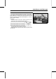

Table Of Contents
- tables
- LIST OF ABBREVIATIONS
- COUNTRY AND AREA CODES
- Units of Mass:
- Units of Volume:
- Units of Force:
- Units of Length:
- Units of Torque:
- Units of Pressure:
- Units of Speed:
- Units of Power:
- Basic Torque for General Fasteners of Engine Parts
- Basic Torque for General Fasteners of Frame Parts
- Throttle Lever Free Play
- Idle Speed
- Water and Coolant Mixture Ratio (when shipping)
- Valve Clearance (when cold)
- Valve Clearance (when cold)
- Belt Width
- Belt Deflection
- Spacers
- Actuator Lever Guide Shoe
- Engine Oil
- Tire Tread Depth
- Standard Tire
- Differential Control Lever Lock Position Length
- Front Final Gear Case Oil
- Rear Final Gear Case Oil
- Pad Lining Thickness
- Rear Brake Lever Free Play
- Brake Pedal Free Play
- Spark Plug Gap
- Brake Light Timing
- Terminal Names
- Sample Diagnosis Sheet
- Engine Doesn't Start, Starting Difficulty
- Poor Running at Low Speed
- Poor Running or No Power at High Speed:
- Connections:
- Throttle Sensor Input Voltage
- Input Voltage at Sensor
- Wiring Connection
- Throttle Sensor Output Voltage
- Idle Speed
- Output Voltage at Sensor
- Wiring Connection
- Throttle Sensor Resistance
- Inlet Air Pressure Sensor Input Voltage
- Input Voltage at ECU
- Inlet Air Pressure Sensor Output Voltage
- Inlet Air Pressure Sensor Output Voltage
- Inlet Air Temperature Sensor Output Voltage
- Output Voltage at ECU
- Inlet Air Temperature Sensor Resistance
- Water Temperature Sensor Output Voltage
- Speed Sensor Input Voltage
- Input Voltage at Sensor
- Speed Sensor Output Voltage
- Output Voltage at Sensor
- Vehicle-down Sensor Power Source Voltage
- Input Voltage at Sensor
- Vehicle-down Sensor Output Voltage
- Output Voltage at Sensor
- Ignition Coil Input Voltage at ECU
- Injector Power Source Voltage
- Power Source Voltage at Injector
- Injector Output Voltage
- Output Voltage at Injector
- Injector Wiring Inspection
- Injector Resistance
- Injector Fuel Line Maximum Pressure
- ECU Grounding Inspection
- ECU Power Source Inspection
- Fuel Pressure (Idling)
- Amount of Fuel Flow
- Pump Operating Voltage at Pump
- Operating Voltage at Pump Connector
- Engine Vacuum Synchronization Vacuum
- Throttle Sensor Output Voltage
- Connections:
- Standard Resistence:
- Radiator Cap Relief Pressure
- Thermostat Valve Opening Temperature
- Rocker Arm Inside Diameter
- Rocker Shaft Diameter
- Cam Height
- Camshaft Bearing Clearance ( 18)
- Camshaft Bearing Clearance ( 22)
- Camshaft Journal Diameter ( 18)
- Camshaft Journal Diameter ( 22)
- Cylinder Compression (Usable Range)
- Cylinder Head Warp
- Valve/Valve Guide Clearance (Wobble Method)
- Valve Seating Surface Outside Diameter
- Valve Seating Surface Width
- Special Tools - Valve Seat Cutters:
- Cylinder Inside Diameter
- Piston Diameter
- Piston/Cylinder Clearance
- Piston Ring/Groove Clearance
- Piston Ring Groove Width
- Piston Ring Thickness
- Piston Ring End Gap
- Actuator Lever Assembly Installation Length
- Measurement Length [E]
- Actuator Lever Assemblies
- Cover Bushing Inside Diameter [A]
- Sheave Bushing Inside Diameter [A]
- Spring Free Length [A]
- Shoe Side Clearance
- Drive Pulley Installation Length [A]
- Measurement Length [D]
- Drive Pulley Covers
- Sheave Bushing Inside Diameter
- Spring Free Length [A]
- Oil Pressure
- Connecting Rod Bend
- Connecting Rod Twist
- Connecting Rod Big End Side Clearance
- Connecting Rod Big End Bearing, Insert/Crankpin Clearance
- Crankpin Diameter
- Crankpin Diameter Marks
- Connecting Rod Big End Inside Diameter Marks
- Big End Bearing Insert Selection
- Crankshaft Runout
- Crankshaft Main Journal Diameter
- Crankcase Main Bearing Bore Diameter
- Shift Fork Ear Thickness
- Shifter Groove Width
- Toe-in of Front Wheels
- Maximum Tire Air Pressure (to seat beads when cold)
- Tire Air Pressure (when cold)
- Drive Bevel Gear Shims for Tooth Contact Adjustment
- Driven Bevel Gear Shims for Backlash Adjustment
- Output Bevel Gear Backlash
- Standard Length of Assembling:
- Standard Length of Assembling
- Front Final Gear Case Coupling Bushing Inside Diameter [B]
- LSD Clutch Torque (When variable differential control lever is r
- LSD Clutch Torque (When variable differential control lever is p
- 1. Pinion Gear Shims for Backlash Adjustment
- 2. Ring Gear Right Shims for Tooth Contact Adjustment
- 3. Ring Gear Left Shims for Tooth Contact Adjustment
- Front Final Bevel Gear Backlash
- Standard Length of Assembling:
- Standard Length of Assembling:
- 6. Pinion Gear Shims for Backlash Adjustment
- 7. Ring Gear Shims for Tooth Contact Adjustment
- 8. Ring Gear Shims for Tooth Contact Adjustment
- Rear Final Bevel Gear Backlash
- Recommended Disc Brake Fluid
- Disc Thickness
- Disc Runout
- Spring Action
- Spring Action
- Tie-rod Length
- Kawasaki-recommended chargers:
- Battery Terminal Voltage
- Terminal Voltage: 11.5 ∼ less than 12.8 V
- Terminal Voltage: less than 11.5 V
- Regulator/Rectifier Output Voltage
- Alternator Output Voltage
- Stator Coil Resistance @20°C (68°F)
- Regulator/Rectifier Resistance (Unit: kΩ)
- Ignition Coil Arcing Distance
- Ignition Coil Winding Resistance
- Ignition Coil Primary Peak Voltage
- Crankshaft Sensor Resistance
- Connections:
- Crankshaft Sensor Peak Voltage
- Ignition Timing
- Starter Motor Brush Length
- Testing Relay
- Radiator Fan Motor Lead Connections:
- Failure Indication Pattern and Failure Part
- Malfunction Mode
- Actuator Internal Resistance
- Actuator Internal Resistance
- Controller Power Supply Voltage
- Speed Sensor Output Voltage
- Controller Output Voltage (at 2WD/4WD Shift Switch OFF, 4WD)
- Controller Output Voltage (at 2WD/4WD Shift Switch ON, 2WD)
- Controller Output Voltage (to Actuators)
- Controller Output Voltage (to speed sensor)
- Controller Output Voltage (to 2WD/4WD shift switch)
- Controller Output Voltage (to engine brake actuator)
- Controller Output Voltage (to 2WD/4WD actuator)
- Forward/Reverse Detecting Sensor Resistance
- Fuel Level Sensor Resistance
- Water Temperature Sensor Resistance
- Testing Relay
- toc
- EMISSION CONTROL INFORMATION
- PLEASE DO NOT TAMPER WITH NOISE CONTROL SYSTEM (US MODEL only)
- Foreword
- General Information
- Before starting to perform an inspection service or carry out a
- Battery Ground
- Edges of Parts
- Solvent
- Cleaning Vehicle before Disassembly
- Arrangement and Cleaning of Removed Parts
- Storage of Removed Parts
- Inspection
- Replacement Parts
- Assembly Order
- Tightening Sequence
- Tightening Torque
- Force
- Gasket, O-ring
- Liquid Gasket, Locking Agent
- Press
- Ball Bearing and Needle Bearing
- Oil Seal, Grease Seal
- Circlips, Cotter Pins
- Lubrication
- Direction of Engine Rotation
- Electrical Wires
- Instrument
- KVF750D8F Left Side View
- KVF750D8F Right Side View
- Frame Number
- Engine Number
- Prefixes for Units:
- Units of Temperature
- Before starting to perform an inspection service or carry out a
- Periodic Maintenance
- The scheduled maintenance must be done in accordance with this c
- The following tables list the tightening torque for the major fa
- Oil Filter Wrench:
- Fuel System
- Throttle Lever Free Play Inspection
- Throttle Lever Free Play Adjustment
- Idle Speed Inspection
- Idle Speed Adjustment
- Air Cleaner Element Cleaning and Inspection
- Air Cleaner Draining
- Fuel Hose Inspection (fuel leak, damage, installation condition)
- Fuel Hose Replacement
- Cooling System
- Engine Top End
- Converter System
- Engine Lubrication System
- Wheels/Tires
- Final Drive
- Brakes
- Front Brake Pad Wear Inspection
- Front Brake Hoses and Connections Inspection
- Front Brake Hose Replacement
- Front Brake Fluid Level Inspection
- Front Brake Fluid Change
- Front Brake Master Cylinder Piston Assembly and Dust Cover Repla
- Front Brake Caliper Fluid Seal Replacement
- Front Brake Caliper Dust Seal and Friction Boot Replacement
- Rear Brake Plates Replacement
- Rear Brake Lever Free Play Inspection
- Rear Brake Pedal Free Play Inspection
- Rear Brake Lever and Pedal Free Play Adjustment
- Steering
- Electrical System
- Joint Boots Inspection
- General Lubrication
- Bolts and Nuts Tightening
- Fuel System (DFI)
- DFI System
- DFI System Wiring Diagram
- FI Indicator Light (LCD) [A]
- Vacuum Gauge Adapter:
- DFI Servicing Precautions
- Outline
- NOTE
- Self-diagnosis Outline
- Throttle Sensor Removal/Adjustment
- CAUTION
- Inlet Air Temperature Sensor Removal/Installation
- Water Temperature Sensor Removal/Installation
- Start the engine and switch the diagnosis mode to Dealer 1 mode
- Speed Sensor Removal
- Vehicle-down Sensor Removal
- Fuel Pump Relay Removal
- Ignition Coil ##1: Ignition Coil for Front Cylinder (Service Code
- Fuel Injector Removal
- Inspection Flow Chart
- CAUTION
- Fuel Pressure Inspection
- Fuel Pump Removal
- Throttle Lever Free Play Inspection
- Idle Speed Inspection
- ISC Valve Removal
- Air Cleaner Element Removal
- Fuel Tank Removal
- Cooling System
- Engine Top End
- Outside Circlip Pliers:
- Camshaft Chain Tensioner Removal
- Rocker Case Removal
- Camshaft Removal
- Cylinder Compression Measurement
- Valve Clearance Inspection
- Cylinder Removal
- This vehicle is equipped with a spark arrester approved for off-
- Converter System
- Engine Lubrication System
- Engine Removal/Installation
- Crankshaft/Transmission
- Outside Circlip Pliers:
- Crankcase Disassembly
- Crankshaft Removal
- Crankshaft Installation
- Connecting Rod Removal
- Connecting Rod Installation
- Crankshaft/Connecting Rod Cleaning
- Connecting Rod Bend Inspection
- Connecting Rod Twist Inspection
- Connecting Rod Big End Side Clearance Inspection
- Connecting Rod Big End Bearing/Crankpin Wear Inspection
- Crankshaft Runout Inspection
- Crankshaft Main Bearing/Journal Wear Inspection
- Shift Lever Removal
- Ball and Needle Bearing Replacement
- Wheels/Tires
- Final Drive
- Dummy Page
- Bearing Puller:
- Output Drive Bevel Gear Removal
- Special Tool -
- Output Drive Bevel Gear Installation
- Output Drive Bevel Gear Disassembly
- Output Drive Bevel Gear Assembly
- Output Driven Bevel Gear Removal
- Output Driven Bevel Gear Installation
- Output Driven Bevel Gear Disassembly
- Output Driven Bevel Gear Assembly
- Output Bevel Gears Adjustment
- Output Bevel Gear (Backlash-related Parts)
- Front Propeller Shaft Removal
- Front Axle Removal
- Front Final Gear Case Oil Level Inspection
- Torque -
- Front Final Gear Case Oil Change
- Variable Differential Control Lever Play Inspection
- Variable Differential Control Lever Play Adjustment
- Variable Differential Control Lever Removal
- Variable Differential Control Lever Installation
- Variable Differential Control Cable Installation
- Variable Differential Control Cable Lubrication
- Variable Differential Control Cable Inspection
- Front Final Gear Case Removal
- Front Final Gear Case Installation
- Front Final Gear Case Disassembly
- Front Final Gear Case Coupling Inspection
- Front Final Gear Case Assembly
- Oil Seal Installation
- Ring Gear Disassembly
- Ring Gear Assembly
- LSD Clutch Torque Inspection
- Pinion Gear Unit Disassembly
- Pinion Gear Unit Assembly
- Front Final Bevel Gear Adjustment
- Front Final Gear Case (Backlash-related Parts)
- Correct Tooth Contact Pattern: No adjustment is required.
- Incorrect Tooth Contact Patterns (Example 1)
- Incorrect Tooth Contact Patterns (Example 2)
- Rear Propeller Shaft Removal
- Rear Axle Removal
- Rear Final Gear Case Oil Level Inspection
- Torque -
- Rear Final Gear Case Oil Change
- Rear Final Gear Case Removal
- Rear Final Gear Case Installation
- Rear Final Gear Case Disassembly
- Rear Final Gear Case Right Cover Assembly
- Rear Final Gear Case Front Cover Assembly
- Rear Final Gear Case Assembly
- Rear Final Bevel Gear Adjustment
- Rear Final Gear Case (Backlash-related Parts)
- Ball or Needle Bearing Inspection
- Brakes
- Suspension
- Inside Circlip Pliers:
- Front Shock Absorber Preload Adjustment
- Front Suspension Arm Removal
- Steering
- Inside Circlip Pliers:
- Steering Stem Removal
- Steering Inspection
- Handlebar Removal
- Frame
- Seat Removal
- Front Carrier Removal
- Front Fender Removal
- Middle Cover Removal
- Front Guard Removal
- Left Footboard Removal
- Trailer Hitch Bracket Removal
- Electrical System
- Light/Dimmer Switch [A]
- Dummy Page
- Timing Light:
- There are a number of important precautions that should be taken
- Wiring Inspection
- Battery Removal
- Alternator Cover Removal
- Special Tool -
- Alternator Cover Installation
- Alternator Rotor Removal
- Alternator Rotor Installation
- Alternator Stator Removal
- Alternator Stator Installation
- Regulator/Rectifier Output Voltage Inspection
- Alternator Inspection
- Regulator/Rectifier Removal
- Regulator/Rectifier Installation
- Regulator/Rectifier Inspection
- Charging System Circuit
- WARNING
- Spark Plug Removal
- Spark Plug Installation
- Spark Plug Cleaning/Inspection
- Spark Plug Gap Inspection
- Ignition Coil Removal
- Ignition Coil Installation
- Ignition Coil Inspection
- Ignition Coil Primary Peak Voltage Inspection
- Crankshaft Sensor Removal
- Crankshaft Sensor Installation
- Crankshaft Sensor Inspection
- Crankshaft Sensor Peak Voltage Inspection
- Alternator Rotor Inspection
- Ignition Timing Test
- Ignition System Troubleshooting
- Ignition System Circuit
- Starter Motor Removal
- Headlight Beam Vertical Adjustment
- Radiator Fan Motor Inspection
- Multifunction Meter Unit Removal
- 2WD/4WD Actuator Removal
- If the drive belt failure detection system activated by abnormal
- Fuel Level Sensor Inspection
- Special Tool -
- Fuel Level Sensor Circuit
- Relay Inspection
- Fuse Removal
- Appendix
- NOTE
- Engine Doesn't Start, Starting Difficulty:
- Poor Running at Low Speed:
- Poor Running or No Power at High Speed:
- Overheating:
- Over Cooling:
- Converter Operation Faulty:
- Gear Shifting Faulty:
- Abnormal Engine Noise:
- Abnormal Drive Train Noise:
- Abnormal Frame Noise:
- Exhaust Smokes Excessively:
- Handling and/or Stability Unsatisfactory
- Brake Doesn't Hold
- Kawasaki Engine Brake Control and Selectable 2WD/4WD System Malf
- Battery Discharged:
- Battery Overcharged:
- NOTE
- EMISSION CONTROL INFORMATION

APPENDIX 17-5
Troubleshooting Guide
Handling and/or Stability Unsatisfactory
Handlebar hard to turn:
Ti re air pressure too low
Steering stem bearing damaged
Steering stem bearing lubrication inade-
quate
Steering stem bent
Damaged steering knuckle joint
Damage tie-rod end
LSD clutch maladjusted (front final gear
case)
Noise when turning:
Damaged side gear or pinion (front final
gear case)
Worn LSD clutch friction plates (Front final
gear case)
Handlebar shakes or excessively vibrates:
Ti re worn
Wheel rim warped
Rear axle runout excessive
Wheel bearing worn
Handlebar clamp loose
Steering stem clamp bolt loose
Handlebar pulls to one side:
Frame bent
Wheel maladjustment
Suspension arm bent or twisted
Steering stem bent
Front or rear tire air pressure unbalanced
Front shock absorber unbalanced
Shock absorption unsatisfactory:
Too hard:
Ti re air pressure too high
Shock absorber maladjusted
Too soft:
Shock absorber oil leaking
Shock absorber spring weak
Ti re air pressure too low
Shock absorber maladjusted
Brake Doesn’t Hold
Front brake:
Air in the brake line
Brake fluid leakage
Brake fluid deteriorated
Primary or secondary cup trouble
Master cylinder scratched inside
Pad overworn or worn unevenly
Oil, grease o n pads and disc
Disc worn or warped
Brake overheated
Rear Brake:
Brake not properly adjusted
Plates worn
Brake parts worn or damaged
Kawasaki Engine Brake Control and
Selectable 2WD/4WD System Malfunction:
Actuators failed
Speed sensor short or open
Forward/Reverse detecting sensor short or
open
Actuator controller failed
Controller 10A fuse blown
Battery disconnected
Battery Discharged:
Battery faulty (e.g., plates sulphated,
shorted through sedimentation, elec-
trolyte level too low)
Battery leads making poor contact
Load excessive (e.g., bulb of excessive
wattage)
Ignition switch trouble
Regulator/rectifier trouble
Alternator trouble
Wiring faulty
Battery Overcharged:
Regulator/rectifier trouble
Battery trouble