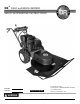
DR® FIELD and BRUSH MOWER SAFETY & OPERATING INSTRUCTIONS Serial No. Order No. Original Language DR Power Equipment Toll-free phone: 1-800-DR-OWNER (376-9637) Fax: 1-802-877-1213 Website: www.DRpower.com Read and understand this manual and all instructions before operating the DR FIELD and BRUSH MOWER.
Table of Contents Chapter 1: General Safety Rules 3 Chapter 2: Setting Up The DR FIELD and BRUSH MOWER 7 Chapter 3: Operating The DR FIELD and BRUSH MOWER 11 Chapter 4: Maintaining The DR FIELD and BRUSH MOWER 15 Chapter 5: Troubleshooting 24 Chapter 6: Parts Lists, Schematic Diagrams And Warranty 28 Conventions used in this manual This indicates a hazardous situation, which, if not avoided, could result in death or serious injury.
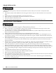
Chapter 1: General Safety Rules Read this safety & operating Instructions manual before you use the DR FIELD and BRUSH MOWER. Become familiar with the operation and service recommendations to ensure the best performance from your machine. If you have any questions or need assistance, please contact us at www.DRpower.com or call toll-free 1-800-DR-OWNER (376-9637) and one of our Technical Support Representatives will be happy to help you.
Safety for Children and Pets Tragic accidents can occur if the operator is not alert to the presence of children and pets. Children are often attracted to the machine and the mowing activity. Never assume that children will remain where you last saw them. Always follow these precautions: • Keep children and pets at least 100 feet from the working area and ensure they are under the watchful care of a responsible adult. • Be alert and turn the machine off if children or pets enter the work area.
Slope Operation Slopes are a major factor related to slip and fall accidents, which can result in severe injury. All slopes require caution. If you feel uneasy on a slope, do not mow it. Always take the following precautions when using this machine on slopes: ALWAYS: • Always mow across the face of slopes; never up and down. Exercise extreme caution when changing direction on slopes. • Always remove objects such as rocks, tree limbs, etc. • Always watch for holes, ruts, or bumps.
• • • • While using the DR FIELD AND BRUSH MOWER, don't hurry or take things for granted. When in doubt about the equipment or your surroundings, stop the machine and take the time to look things over. Make sure that you have 100% control of the mower at all times. Do not operate the machine when under the influence of drugs, alcohol, or medication. Watch for traffic when mowing near roadways. Use the machine only in daylight.
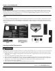
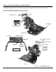
Chapter 2: Setting Up The DR FIELD and BRUSH MOWER It may be helpful to familiarize yourself with the controls and features of your DR FIELD and BRUSH MOWER as shown in Figure 1 before beginning these procedures. If you have any questions at all, please feel free to contact us at www.DRpower.com.
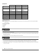
Specifications Engine Fuel Capacity Cutting Capacity Cutting Width Cutting Height speeds Tires Machine Dimensions Machine Weight Shipping Dimensions Shipping Weight Premier Pro See Engine Owners See Engine Owners Manual for details Manual for details Pro-XL See Engine Owners Manual for details 2-1/2 Gal. (9.5 L) 4' –High Grass & Weeds; 2"-Thick Saplings 26" 4" 4 Forward; 1 Rev. 18" x 6-1/2" Lugged 78"L x 33"W x 41"H 334 lbs. 55"L x 46"W x 46"H 459 2-1/2 Gal. (9.
Pin Before attaching the deck, be sure the spark plug wire(s) is disconnected. 6. Attach the Deck to the Power Unit following the directions in the next section. The Belt is stored below the black Pulley Cover. Collar 7. If assembling the Lawn Deck, mount the front Caster Wheels before attaching the Deck to the Power Unit. NOTE: Find the Safety and Operating Instructions and the Caster Wheels for the Lawn Deck (if ordered) tucked in one of the cardboard corner supports.
Adding Oil and Gasoline • • You must add oil before starting the engine. This machine is shipped without oil. Traces of oil may be in the reservoir from factory testing, but you must add oil before starting the engine. Fill the reservoir slowly, checking the level frequently to avoid overfilling. To get an accurate reading when checking the oil level: - the machine should be on a level surface. - the dipstick SHOULD be screwed down on Briggs & Stratton Engines to ensure an accurate oil level reading.
Chapter 3: Operating The DR FIELD and BRUSH MOWER This chapter covers the procedures for starting and stopping your new DR FIELD and BRUSH MOWER and discusses basic operation features. You may find it helpful to review the DR FIELD and BRUSH MOWER Controls and Features in Figure 1 on page 8 before reading this chapter.
Before Starting the Engine 1. Check the oil level every time you use the machine. 2. Check the gas level. 3. Open the Fuel Shut-Off Valve, which is located on the bottom of the Fuel Tank and accessed from the rear (Figure 1 on page 8), if your model is equipped with one. Starting 1. Move the Shift Lever to N (Neutral). (Figure 1 on page 8. NOTE: The Shift Lever MUST be in NEUTRAL and the Blade Engage Button pushed DOWN, or the Engine will not start. 2.
4. Move the Throttle Control to the IDLE position. 5. Turn the Key to the OFF position and remove it for safety. NOTE: If your machine is equipped with a Fuel Shut-Off Valve, close it when transporting or storing the Mower. Obstacle Tips Dealing with obstacles in the terrain is easy with your new DR FIELD and BRUSH MOWER. The following section explains how to approach most common obstacles.
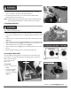
Cutting Brush and Saplings 1. When cutting woody material, small saplings, etc., allow the machine to ride up and over material slowly. Adjust your forward speed to varying conditions (Figure 9). 2. After cutting brush, etc., you may want to mow over it again to remove any remaining branches. It works best to mow from the trunk end toward the top as brush lies on the ground. Reverse 1. Be very careful of your footing when operating the machine in reverse. Know what's behind you and take your time.
Chapter 4: Maintaining The DR FIELD and BRUSH MOWER Regular maintenance is the way to ensure the best performance and long life of your machine. Please refer to this manual and the engine manufacturer's owner's manual for maintenance procedures. Service intervals listed in the checklist below supersede those listed in the engine manufacturer's owner's manual. Some of the following procedures require access to the underside of the machine.
Charging the Battery Operate the Mower Engine for at least 45 minutes to maintain proper Battery charge. If the Battery loses its charge, you'll need to use a trickle Charger (like the DR Battery Charger) to recharge it. The Charger should have an output of 12 volts at no more than 2 amps. • At 1 amp, you may have to charge the Battery for as long as 48 hours. • At 2 amps, you may have to charge the Battery for as long as 24 hours.
1. There is one Grease Fitting below the black Belt Guard that needs lubrication (Figure 11): • The Belt Idler Arm should have 1-2 pumps of Grease every 25 operating hours. NOTE: Over greasing will cause grease to leak out of the seals onto the Mower Drive Belt. Unless instructed otherwise, pump only until you feel slight resistance (1-2 pumps). 2. You should lubricate the Drive Chain with SAE 30 oil every 25 operating hours—more often if you operate the machine in extremely dusty or wet conditions.
3. Remove the Belt from the Pulley (Figure 16), and then drop it from the Engine Pulley below the machine. 4. To mount the Belt, follow the above procedure in reverse. To Replace the Drive Belt Belt Removed Before performing any maintenance procedure or inspection, stop the engine, wait five (5) minutes to allow all parts to cool. Disconnect the spark plug wire(s), keeping it away from the spark plug(s). Figure 16 Remove Pin and Collar Use only DR belts on your machine.
9. Loosen the Belt Retainer Bolts on the outside of the Frame (one on each side) and slide the Retainer back (Figure 20). 10. Remove the Belt. 11. To mount the new Belt, reverse the above procedure. Removing and Replacing the Blade Before performing any maintenance procedure or inspection, stop the engine, wait five (5) minutes to allow all parts to cool. Disconnect the spark plug wire(s), keeping it away from the spark plug(s).
2. Loosen the Lower Nut on the Spring side of the Bracket by 1/8" to 1/4", and then tighten the Nut on the Upper side against the Bracket. Check the tension on the Wheel Clutch Lever and repeat the adjustment as needed. If you over tighten the wheel clutch cable, the machine may lurch forward when shifting into gear. Use caution when shifting into gear. Test adjustment using the procedure on page 19.
Adjusting the Differential Lock In/Out Cable Hex Flat In-Line Adjuster Before performing any maintenance procedure or inspection, stop the engine, wait five (5) minutes to allow all parts to cool. Disconnect the spark plug wire(s), keeping it away from the spark plug(s). NOTE: If the Differential will not Lock In or Out, the Cable may need adjustment. Clockwise to tighten 1. Locate the Differential Lock In/Out Cable along the right Handlebar.
Adjusting the Parking Brake Parking Brake Nut Before performing any maintenance procedure or inspection, stop the engine, wait five (5) minutes to allow all parts to cool. Disconnect the spark plug wire(s), keeping it away from the spark plug(s). Tools needed: • 1/2" Open End Wrench 1. Tighten or loosen the Parking Brake Adjusting Nut as needed (Figure 28). Tightening the Nut (clockwise) will increase pressure and loosening the Nut (counterclockwise) will decrease the pressure on the Brake Pad.
Disposing of the Battery Responsibly The Battery is a sealed lead-acid Battery. Recycle or dispose of it in an environmentally sound way. • Do not dispose of a lead-acid Battery in a fire; the Battery may explode or leak. • Do not dispose of a lead-acid Battery in your regular, household trash. Law in most areas prohibits incinerating, disposing in a landfill, or mixing a sealed lead-acid Battery with household trash.
Chapter 5: Troubleshooting Most problems are easy to fix. Consult the Troubleshooting Table below for common problems and their solutions. If you continue to experience problems, contact us at www.DRpower.com or call toll-free 1-800-DR-OWNER (376-9637) for support. Before performing any maintenance procedure or inspection, stop the engine, wait five (5) minutes to allow all parts to cool. Disconnect the spark plug wire(s), keeping it away from the spark plug(s).
Before performing any maintenance procedure or inspection, stop the engine, wait five (5) minutes to allow all parts to cool. Disconnect the spark plug wire(s), keeping it away from the spark plug(s). Troubleshooting Table (Cont.) SYMPTOM POSSIBLE CAUSE Engine runs fine but the machine will not move. ⇒ The Drive Belt is broken or out of adjustment. See page 19. ⇒ The Transmission may be defective, visit our web site at www.DRpower.com for assistance. Machine is hard to get into reverse.
Before performing any maintenance procedure or inspection, stop the engine, wait five (5) minutes to allow all parts to cool. Disconnect the spark plug wire(s), keeping it away from the spark plug(s). Troubleshooting Table (Cont.) 26 SYMPTOM POSSIBLE CAUSE The Wheel Drive Clutch and/or Brake lever will freeze up during cold weather operation. ⇒ Moisture is getting into the Cable housing(s) and freezing.
CONTACT US AT www.DRpower.
Chapter 6: Parts Lists, Schematic Diagrams And Warranty Parts List - Handlebar Assembly NOTE: Part numbers listed are available through DR Power Equipment.
Schematic – Handlebar Assembly 081008 CONTACT US AT www.DRpower.
Parts List – Power Assembly NOTE: Part numbers listed are available through DR Power Equipment. Ref# Part# Description Ref# Part# Description 01 Muffler, 18 HP Honda Muffler, 16 & 18HP (Kawasaki) Nut, 5/16"-18 Cable, Ground, 16" Wire Harness, B&S Wire Harness, B&S, 13.
Schematic – Power Assembly 031810 CONTACT US AT www.DRpower.
Parts List – Brush Deck Assembly NOTE: Part numbers listed are available through DR Power Equipment. Ref# Part# Description Ref# Part# 01 02 03 04 05 150911 150641 164451 160071 160091 16 17 5.1 06 07 08 09 10 11 106401 187351 151141 150721 123211 110761 160611 160511 225781 225791 160891 100481 101771 150681 Spindle Housing, Brush Deck Anti-Wrap Guard, 4 Hole Mount Pulley, V-Belt, 8.5" OD Nut, Nylon Lock, 5/8"-18 Shaft, Spindle, w/Bearing & Woodruff Key Woodruff Key, .188" THK x .
Schematic – Brush Deck Assembly 080912 CONTACT US AT www.DRpower.
Parts List – Frame and Drive Assembly NOTE: Part numbers listed are available through DR Power Equipment. Ref# Part# Description Ref# Part# Description 01 02 03 04 05 06 07 08 09 10 11 12 13 14 15 16 17 18 19 20 21 22 23 24 Frame, Main Bolt, 5/16"-18 x 1", HCS, GR2 Guard, Chain Nut, Nylon Lock, 5/16"-18, Lo-Profile Nut, 5/16"-18 Washer, Flat, 1/4" USS Spring, Extension, .750" OD x FL Bushing, .328" ID, .500" OD, 2.32" L Pulley, Flat Idler, 1.88" OD, .
Schematic – Frame and Drive Assembly 081008 CONTACT US AT www.DRpower.
Wiring Diagram – Briggs and Stratton Electric Start 031810 36 DR® FIELD and BRUSH MOWER
Wiring Diagram – Kawasaki Electric Start 031810 CONTACT US AT www.DRpower.
Notes: 38 DR® FIELD and BRUSH MOWER
DR® FIELD and BRUSH MOWER 2-Year Limited Warranty Terms and Conditions The DR® FIELD and BRUSH MOWER is warranted for two (2) years against defects in materials or workmanship when put to ordinary and normal consumer use; ninety (90) days for any other use. For the purposes of all the above warranties, “ordinary and normal consumer use” refers to non-commercial residential use and does not include misuse, accidents or damage due to inadequate maintenance.
Daily Checklist for the DR FIELD and BRUSH MOWER To help maintain your DR FIELD and BRUSH MOWER for optimum performance, we recommend you follow this checklist each time you use your machine. Before performing any maintenance procedure or inspection, stop the engine, wait five (5) minutes to allow all parts to cool. Disconnect the spark plug wire(s), keeping it away from the spark plug(s). [ [ [ [ [ [ ] ] ] ] ] ] Check the engine oil level. Check the gas Level Check the general condition of the Mower, e.