® DR TRIMMER/MOWER™ Assembly & Operating Instructions Model: • SPRINT® Please read these instructions and the Engine Manufacturer's Owner's Manual before you assemble and use your DR® TRIMMER/MOWER™.
And congratulations on your purchase of a new DR® TRIMMER/MOWER™! We have done our utmost to ensure that your DR® will be one of the most trouble-free and satisfying pieces of equipment you have ever owned. Please let us know of any questions or problems you may have. We want to answer or correct them as quickly as possible. (When you do call or write, please have your serial number and/or order number handy—it will speed things up!) We also hope to hear from you on how much you like your new helper.
ii DR® TRIMMER/MOWER™ Assembly & Operating Instructions
Table of Contents SAFETY INSTRUCTIONS ...............................................................................................................................................1 Dress Appropriately.........................................................................................................................................................1 Preparation................................................................................................................................................
Safety Instructions We want you to enjoy years of productive use from your DR® TRIMMER/MOWER™. We don't want you to get injured, so please take a few moments to read the following guidelines for safely operating your new machine. Dress Appropriately · Always wear protective goggles (provided with your DR® TRIMMER/MOWER™) while mowing, to protect your eyes from possible thrown objects. · Wear shoes with non-slip treads when using your DR® TRIMMER/MOWER™. If you have safety shoes, we recommend wearing them.
· As with any trimmer, the tips of the cutting cords on the DR® TRIMMER/MOWER™ can throw sticks, small stones, gravel, and bits of debris for long distances at great velocity. The faster the cutting cords are spinning, the farther debris may be thrown. Do not move over loose materials such as gravel or mulch with the trimmer head spinning. Doing so could cause personal injury or property damage from thrown objects. · Never allow children or animals near the work area.
Trimmer Parts & Components The following parts and assembly components should be in your DR® TRIMMER/MOWER™ package. Please check your shipping box(es) and parts package(s) for the items listed below. If your shipment is incomplete or if you have any questions, please call us TOLL-FREE 1(800)DROWNER (376-9637).
Assembly Components Figure 1 4 DR® TRIMMER/MOWER™ Assembly & Operating Instructions
Assembly WARNING: Do not attempt to start the engine until all assembly steps are complete, and you have ADDED GAS AND OIL to the engine. Please Note: Your trimmer may look slightly different than some of the photos shown in this manual.
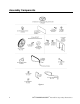
4. Insert the axle through the hole in the bushing in the side of the housing (Figure 5). Push the axle through both axle holes in the frame (Figure 5). Be sure the axle is over the black control cable. 5. Mount the other wheel with the open portion of the hub facing in toward the frame. Mount the retaining ring so it is flush with the axle and tighten the set screw (Figure 6). Figure 5 Figure 6 Step 2: Attach the Rubber Stone Guard 1. Mount the two black clamps on the rubber stone guard.
Step 4: Install the Handlebars A) Lower Handlebar Note: There are 2 U-bolts, 4 washers, and 4 lock nuts in your parts bag that will be needed for the lower handlebar assembly. 1. With the control cables on the inside of the handlebars, position the lower handlebar over the bolt holes in the trimmer frame (Figure 8). 2. Mount one of the U-bolts through the hole in the frame and handlebar from the inside facing out (Figure 8). Repeat on the other side.
To adjust the height of the handlebars, loosen the lock nuts on the U-bolts. Push the handlebars forward for more height, backward for less. Then tighten the nuts securely. Step 5: Attach the Acrylic Engine Shield Use the four remaining sets of 5/8" long bolts and lock nuts to attach the acrylic engine shield. We have found it's easiest to tip the machine back on its handlebars in order to reach the underside. 1.
Step 9: Connect the Battery Wires (Electric-Starting models only) To prevent the battery from discharging during shipment, all electric-starting trimmers are shipped with the black, negative battery wire disconnected. Connect the two black wires by pushing the plastic ends together (Figure 12). See the red wires for comparison. The wires are located on the left front side when standing in the operator's position.
Controls & Features Please Note: Manual-Starting Model shown.
Starting & Operating WARNING! THIS MACHINE IS SHIPPED WITHOUT OIL! TRACES OF OIL MAY BE LEFT IN THE RESERVOIR FROM FACTORY TESTING, BUT YOU MUST ADD THE RECOMMENDED AMOUNT OF OIL BEFORE STARTING THE ENGINE. Please Note: Manual-Starting model is pictured below. Electric-Starting 1. Push the throttle control lever on the right side of the handlebar (Figure 13) all the way forward to the START position. 2. Prime the engine. Make sure you completely cover the air hole on the primer bulb (Figure 14).
Stopping the Engine Move the throttle lever back to the STOP position (Figure 13). Note that on Electric-Starting Models the key does not stop the engine. The key has a pressure lock that prevents it from vibrating loose during operation. If you wish to remove the key, push it in and then quickly and firmly pull it out. If the key is difficult to remove, spray FLUID FILM® or a comparable lubricant into the key hole.
Cutting Cords WARNING: Turn the engine off when installing or changing cutting cords. Two thicknesses of cutting cord ship with your DR® TRIMMER/MOWER™: Heavy-duty (130 mil) Orange and Extra Heavy-duty (155 mil) Green. Figure 15 shows how the cords are installed at the factory. Notice how the cords are installed before you replace them. Note: Before trimming, always spin new cords for a few seconds so they pull tight and set.
Trimming and Mowing Methods Note: The cutting cords cut one to two inches outside of the wheel width. Many owners like to mow easy, open areas with their regular riding or walk-behind mower, then finish trimming all the odd and hard-to-reach spots with the DR® TRIMMER/MOWER™. The DR® TRIMMER/MOWER™ discharges cut material to the right. Always try to cut and trim with the uncut tall grass or weeds at the left (Figure 16).
If Cords Slip There are several options for installing the cutting cords. Experimenting in different conditions with different cutting cords is a good way to find the best method. Below are some suggestions: Figure 17 · When using the standard installation method, wrap the cutting cord through the middle loop twice (the thicker, green cord is stiff, but it can be done) as shown in Figure 17 . This will help prevent the cords from slipping.
Adjusting the Cutting Height One cutting height adjustment disk is already installed on your machine, just above the Mow-Ball™ Support. An additional disk is included in your product package, but you can order more. We recommend you try trimming with one disk before experimenting with additional disks. The cords will cut approximately 1-1/2" to 2" off the ground with one disk installed. If the cut is too low or if you're cutting very tall or heavy grass, you may want to try using an additional disk.
4. Reassemble the components in the order shown in Figure 22, adding the additional cutting height disk above or below the one already installed. • Be sure bearing shield washer is beveled side up. • Be sure to align the notches in the cutting height disks and the Mow-Ball™ Support before completing assembly. • Check the head of the Mow-Ball™ Support bolt. It should sit in the groove (square washer) at the bottom of the MowBall™ Support. 5.
Heavy Growth Take your time in heavy growth. If the machine can't do it all in one pass, overlap half of the cutting swath. If the grass is very thick and heavy, try raising the trimmer head off the ground a few inches by pushing down on the handlebar. Cut the material at this height, and then make a second pass with the Mow-Ball™ Support on the ground (Figure 24). EASE the DR® TRIMMER/MOWER™ into denser growth.
Windrows The DR® TRIMMER/MOWER'S cutting cords cut even tall grass in just one pass, so you can collect clippings and leaves for mulch. The machine ejects cut material to its right, so you can use it like a lawn broom to make windrows for easy raking (Figure 26). Firebreaks Use the DR® as a labor-saving tool to cut material when creating firebreaks.
Maintenance For Engine Maintenance, Please Refer to the Engine Manufacturer's Owner's Manual. IMPORTANT: Because of the extreme conditions the DR® TRIMMER/MOWER™ is often used in, air filters and oil should be changed more frequently than is recommended in your Engine Manufacturer's Owner's Manual. Please follow these recommendations: Paper Air Cartridge: Should be replaced every 25 hours of operation. Oil: Should be drained and replaced every 25 hours of operation.
Battery Care (Electric-Starting models only) Proper care can extend the life of a battery. Follow these recommendations to ensure your battery's best performance and long life: · Do not continue to crank the engine if the battery is low. · Try to keep the battery at full charge to maximize its life. If the machine is not in use, the battery should be charged every three months. · Store an unused battery in a dry area that does not freeze. · Do not charge an already charged battery.
· · The wiring harness consists of a set of wires that lead from the ignition switch to the battery. Disconnect and reconnect the battery wires (black to black and red to red) and check the wire connections at the key switch. Call one of our Customer Service Representatives TOLL-FREE 1(800)DR-OWNER(376-9637) for assistance. To Remove the Mow-Ball™ Support Assembly WARNING: Before performing any maintenance procedures, the engine should be stopped and the spark plug wire disconnected.
To Reassemble the Mow-Ball™ Support Assembly WARNING: Before performing any maintenance procedures, the engine should be stopped and the spark plug wire disconnected. Caution: An improper installation may cause damage to the bearings. Please follow these directions carefully. Tool Needed: • Phillips head screwdriver Note: If you removed and are reinstalling the Wagner Anti-Wrap Device, be sure the bracket is flush with or slightly above the bottom edge of the bearing housing shaft— not below it. 1.
To Partially Lower the Bearing Housing Assembly (to remove debris) WARNING: Before performing any maintenance procedures, the engine should be stopped and the spark plug wire disconnected. Tools Needed: • 1/2" socket • 1/2" wrench If possible, set the machine up on a bench. Do not tip the machine all the way back on its handlebars unless you have drained the gas and oil. 1. Remove the three bearing housing nuts (Figure 30) and carefully lower the bearing housing assembly (Figure 31) from the frame.
3. Turn the Mow-Ball™ Support assembly by hand. It should turn freely, without resistance. If it doesn't turn freely or you hear a grinding noise, the bearings may be worn and you may need to replace the bearing housing assembly. 4. Call one of our Customer Service Representatives TOLL-FREE 1(800)DR-OWNER(376-9637) for information about replacing the bearing housing assembly.
To Replace the Belt Figure 33 shows the belt and pulley system from the underside of the machine. WARNING: Before performing any maintenance procedures, the engine should be stopped and the spark plug wire disconnected. 1. Remove the old belt. Take the new belt and loop it over the bearing housing pulley and in between the belt guides (Figures 33 & 34). 2.
To Adjust the Belt Tension Using the Trimmer Control Cable If the trimmer head stops spinning when the trimmer head control bar is engaged and the machine is operating under a heavy load, the belt may be too loose and the trimmer control cable may need to be adjusted to put more tension on it. Before making any adjustments to the trimmer control cable, check that the belt is mounted on the correct side of the idler pulley (see page 26, Figure 33), and is not frayed, worn or stretched.
Troubleshooting WARNING: Before performing any maintenance procedures, the engine should be stopped and the spark plug wire disconnected. Engine won't start manually Þ Are you priming? Push the primer bulb 3 to 5 times, releasing completely each time. (Please refer to the Engine Manufacturer's Owner's Manual for engine-specific procedures.) Þ Are you using fresh, clean gas? If it’s old, change it. Use a fuel stabilizer if you keep gas longer than two weeks or so.
Engine lacks power or is not running smoothly (continued) Þ Is the air filter clean? If it’s dirty, change it following the procedure in the Engine Manufacturer's Owner's Manual. (Please refer to the Engine Manufacturer's Owner's Manual for engine-specific procedures.) Þ Is the throttle cable attached to the engine and moving freely? Þ Are the blower housing, throttle linkage and cooling fins free of debris? Clean them following the instructions in the engine manufacturer's owner's manual.
Trimmer head won't spin (continued) Þ If the head still will not spin, follow the procedure for To Adjust the Belt Tension Using the Trimmer Control Cable in the maintenance section of this manual. Þ If none of the above helps, call 1(800)DROWNER(376-9637) for advice and assistance. Trimmer head keeps spinning Þ Is your v-belt properly aligned? Check it against the diagram in the Belt section of this manual. Make sure the belt is inside the idler pulley, that the spring on the idler pulley is in place.
Mow-Ballä Support is wearing too quickly Þ Are you pushing the trimmer head down into the ® ground? The DR TRIMMER/MOWERä works best with a light touch, with the Mow-Ballä Support resting easily on the ground. Þ Are you hitting the Mow-Ballä Support against rocks, concrete driveways or other hard obstacles? Try approaching them slowly, and from different directions, to avoid unnecessary wear. For technical assistance call one of our Technical Representatives TOLL-FREE 1(800)DR-OWNER (376-9637).
Parts List Please Note: Reference numbers match the circled numbers on the schematic drawing. Not all parts listed appear on the drawing.
Schematic Drawing Figure 36 DR® TRIMMER/MOWER™ Assembly & Operating Instructions 33
Daily Checklist for the DR® TRIMMER/MOWER™ To help maintain your DR® for optimum performance, we recommend you follow this checklist each time you use it. See the appropriate section of this manual or your Engine Manufacturer's Owner's Manual for instructions. 4 GAS: Fill the gas tank with clean, fresh, unleaded gas. Be careful not to spill gas on the engine shield. Gasoline will cloud the acrylic. If gas does spill on the shield, rinse it immediately with soap and water.