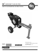
` ® RAPIDFIRE™ LOG SPLITTER DR SAFETY & OPERATING INSTRUCTIONS Serial No. Order No. Original Language DR Power Equipment Toll-free phone: 1-800-DR-OWNER (376-9637) Fax: 1-802-877-1213 Website: www.DRpower.com Read and understand this manual and all instructions before operating the DR RAPIDFIRE LOG SPLITTER.
Table of Contents Chapter 1: General Safety Rules............................................................................................................................................................ 3 Chapter 2: Setting Up The DR RAPIDFIRE LOG SPLITTER ................................................................................................................. 7 Chapter 3: Operating The DR RAPIDFIRE LOG SPLITTER .....................................................................................
Chapter 1: General Safety Rules Read this Safety & Operating Instructions manual before you use the DR RAPIDFIRE LOG SPLITTER. Become familiar with the operation and service recommendations to ensure the best performance from your machine. If you have any questions or need assistance, please contact us at www.DRpower.com or call toll-free 1-800-DR-OWNER (376-9637) and one of our Technical Support Representatives will be happy to help you.
Protecting Yourself and Those Around You This is a high-powered machine, with moving parts operating with high energy. You must operate the machine safely. Unsafe operation can create a number of hazards for you, as well as anyone else in the nearby area. Always take the following precautions when using this machine: Keep in mind that the operator or user is responsible for accidents or hazards occurring to other people, their property, and themselves.
Safety with Gasoline - Powered Machines Gasoline is a highly flammable liquid. Gasoline also gives off flammable vapor that can be easily ignited and cause a fire or explosion. Never overlook the hazards of gasoline. Always follow these precautions: Never run the engine in an enclosed area or without proper ventilation as the exhaust from the engine contains carbon monoxide, which is an odorless, tasteless, and a deadly poisonous gas.
General Safety Operating this Log Splitter safely is necessary to prevent or minimize the risk of death or serious injury. Unsafe operation can create a number of hazards for you. Always take the following precautions when operating this Log Splitter: Your Log Splitter is a powerful tool, not a plaything. Exercise extreme caution at all times. The machine is designed to split logs. Do not use it for any other purpose. Know how to stop the Log Splitter quickly; see “stopping the engine” in chapter 3.
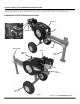
Chapter 2: Setting Up The DR RAPIDFIRE LOG SPLITTER It may be helpful to familiarize yourself with the controls and features of your DR RAPIDFIRE LOG SPLITTER as shown in Figure 1 before beginning these procedures. If you have any questions at all, please feel free to contact us at www.DRpower.com.
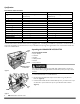
Specifications MECHANICAL SPECIFICATIONS Engine Wedge Height Log Capacity Cycle Time Tires H-Beam Height Overall Height Overall Length Width Splitter Weight w/ Tray Splitter Weight w/out Tray Flywheel Weight Flywheel Diameter Flywheel Max RPM Manual Start Subaru (refer to the engine manual for specifications) 6-1/4" Length 24 inches, Diameter 30 inches* 3 seconds (approx.) 18" 29 inches 48 inches 84 inches w/Tray 35 inches 499 lbs. (226kg) 467 lbs. (212kg) 74 lbs.
4. Remove the Lag bolt that secures the Front Leg to the Pallet with a 9/16" Wrench (Figure 4). Strap 5. Undo the Strap from the Splitter and Pallet. 6. Remove the front Wheel Chocks from the Pallet with a Hammer and Pry Bar. 7. Rotate the Handles up and lock them into position with the Detent Pins from the Product Package (Figure 5). Lag Bolt 8. With the help of another person carefully roll the Log Splitter from the Pallet.
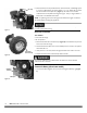
Gas Cap 6. Remove the Gas Fill Cap and fill the Gas Tank with fresh, unleaded gas (with a minimum of 85 Octane) to approximately 1" to 1-1/2" below the top of the fill neck to allow for fuel expansion (Figure 7). Be careful not to overfill. Install the Gas Fill Cap before starting the engine. See your Engine Owner’s Manual for more detailed information. NOTE: To refill the gas tank, turn the engine OFF and let the engine cool at least five minutes before removing the gas fill cap.
Chapter 3: Operating The DR RAPIDFIRE LOG SPLITTER It may be helpful to better familiarize yourself with the features of your Log Splitter by reviewing Figure 1 in Chapter 2 before beginning the steps outlined in this chapter. Read and understand all instructions, safety precautions, and/or warnings listed in “Chapter 1 General Safety Rules” before operating this DR RAPIDFIRE LOG SPLITTER.
Splitting Note: All logs should be no longer than 24". Do not place your hands on the ends of the log when loading the Log Splitter. This is a very UNSAFE method and could result in injury to your hands (Figure 13). Do not reach or step across the rail while the Log Splitter is running. This is a very UNSAFE method which could cause personal injury or even death. Figure 13 Never attempt to split wood across the grain. The Log Splitter was not designed for cross-grain splitting.
Chapter 4: Maintaining The DR RAPIDFIRE LOG SPLITTER Regular maintenance is the way to ensure the best performance and long life of your machine. Please refer to this manual and the engine manufacturer's owner's manual for maintenance procedures. Service intervals listed in the checklist below supersede those listed in the engine manufacturer's owner's manual. Before performing any maintenance procedure or inspection, stop the engine, wait five (5) minutes to allow all parts to cool.
3. Grease the Rack Teeth with All Purpose Grease (Figure 20). Rail 4. Push the Carriage assembly back into starting position, reconnect both Return Springs and cut the strings off. Changing Engine Oil One of the easiest methods to remove oil from this Engine is to use a siphon style Oil Extractor. If you do not have one you can purchase it from us at www.DRpower.com. Grease on Teeth Figure 20 Tools and Supplies needed: Oil Extractor Clean Container for used Oil 1.
1. Remove the Return Springs as described in step 1 of “Greasing The Rack and Pinion” on page 13 (Figure 19). 2. Pull the Carriage out approximately half way and remove the three Bolts and Lock Washers on each side of the Carriage and Rack assembly as you support and remove the Carriage Hold Downs (Figure 23). Note the position of the Roller Bearings. Bolts and Locknuts 3. Pull the Wear Plate out from under the Carriage and check thickness.
3. Remove the Bolt, Lock Washer and large Flat Washer from the Clutch with a 1/2" Wrench and remove the Clutch from the Engine Shaft (Figure 27). Engine Shaft Note: To remove and replace the Clutch hardware, use a dead blow hammer to hit the Wrench to enable you to create torque and prevent movement of the Engine Shaft. Clutch Built in Key Lock Washer Bolt 4. Install the new Clutch and secure with the Bolt, Lock Washer and large Flat Washer with a 1/2" Wrench. 5. Install the Belts and Belt cover.
Changing and Adjusting Belts (When Tensioner adjustment no longer prevents Belts from slipping excessively) Belt Guard Note: Both Belts must be replaced at the same time due to stretching of the old Belts. Tools and Supplies needed: Side Hardware Two 7/16" Wrenches Two 9/16" Wrenches 1. Remove one Bolt and Locknut on the left side of the Belt Guard with two 7/16" Wrenches (Figure 32). 2. Remove the two lower sets of Bolts and Locknuts at the front of the Belt Guard with two 7/16" Wrenches.
Replacing the Wheels Wheel Assembly Tools and Supplies needed: Needle Nose Pliers Jack Large Flat Washer Cotter Pin The Splitter must be supported carefully so it does not tip over when jacking or it could cause Splitter damage or personal injury. 1. Jack the Splitter until a Wheel is just off the ground. Figure 36 2. Remove the Cotter Pin by straightening the ends and pulling it from the hole in the Axle with Needle Nose Pliers (Figure 36). 3.
Charging the Battery Operate the Engine for at least 45 minutes to maintain proper Battery charge. If the Battery loses its charge, you will need to use a When you are finished charging the battery, disconnect the charger from the outlet first, then disconnect the battery charger wires from the battery. If you leave the battery charger wires connected to the battery, the battery will discharge itself back into the charger. trickle charger (like the DR Battery Charger) to recharge it.
Chapter 5: Troubleshooting Most problems are easy to fix. Consult the Troubleshooting Table below for common problems and their solutions. If you continue to experience problems, contact us at www.DRpower.com or call toll-free 1-800-DR-OWNER (376-9637) for support. Before performing any maintenance procedure or inspection, stop the engine, wait five (5) minutes to allow all parts to cool. Disconnect the spark plug wire, keeping it away from the spark plug.
Troubleshooting Table (Continued) Before performing any maintenance procedure or inspection, stop the engine, wait five (5) minutes to allow all parts to cool. Disconnect the spark plug wire, keeping it away from the spark plug. SYMPTOM POSSIBLE CAUSE Machine does not seem to have full splitting power. The belts may be too loose and slipping. Adjust or replace belts as needed. Operator Lever not engaging rack with pinion gear. Clean wood chips or other debris from under rack.
Chapter 6: Parts Lists and Schematic Diagrams Parts List - FRAME ASSEMBLY NOTE: Part numbers listed are available through DR Power Equipment. Ref# Part# Description Ref# Part# Description 1 2 3 4 5 6 7 8 9 10 11 11239 11985 15043 11075 29469 11238 11073 18655 18064 29442 22151 12 13 14 15 22232 29441 18031 29815 Washer, Flat, 3/8", USS Bolt, HCS, 3/8-16 X 1.
Schematic – FRAME ASSEMBLY CONTACT US AT www.DRpower.
Parts List – DRIVE ASSEMBLY NOTE: Part numbers listed are available through DR Power Equipment. Ref# Part# Description Ref# Part# Description 1 2 3 4 5 6 7 8 9 10 11 12 13 14 15 16 17 18 19 20 21 22 23 24 Washer, Flat, 3/8", USS Bolt, HHCS, 3/8-16 X 1-1/4", GR5 Nut, Nylon Lock, 3/8-16 Cradle, Spring, Carriage Washer, Flat, 1/4" Washer, Lock, Split, 5/16" Bolt, HHCS, 1/4-20 X 1.00", GR5, ZP Nut, Finish, 1/4-20, ZP Washer, Lock, 3/8" Bolt, HCS, 5/16-18 X 1.
Schematic – DRIVE ASSEMBLY CONTACT US AT www.DRpower.
Parts List – LINKAGE AND BATTERY ASSEMBLY NOTE: Part numbers listed are available through DR Power Equipment. Ref# Part# Description Ref# Part# Description 1 2 3 4 5 6 7 8 9 10 11 12 13 14 15 16 Washer, Flat, 3/8", USS Bolt, HCS, 3/8-16 X 1.5" Bolt, HHCS, 3/8-16 X 1-1/4", Gr5 Nut, Nylon Lock, 3/8-16 Nut, Finish, 1/4-20, ZP Washer, Lock, 3/8" Washer, Flat, 5/16" Nut, Nylon Lock, 1/4-20 Bearing, Yoke, Roller, 1.
Schematic – LINKAGE AND BATTERY ASSEMBLY CONTACT US AT www.DRpower.
Daily Checklist for the DR LOG SPLITTER To help maintain your DR LOG SPLITTER for optimum performance, we recommend you follow this checklist each time you use your Log Splitter. Before performing any maintenance procedure or inspection, stop the engine, wait five (5) minutes to allow all parts to cool. Disconnect the spark plug wire, keeping it away from the spark plug. [ [ [ [ [ [ [ ] ] ] ] ] ] ] Check the Engine Oil and Gas Tank level. Check that Engine is clean of debris.