OWNER'S MANUAL MODEL NO. PO14542B 14.5 HP 42 Inch Lawn Tractor For Parts and Service, contact our authorized distributor: call 1-800-849-1297 For Technical Assistance: call 1-800-829-5886 176038 11.21.00 RD PRINTED IN U.S.A.
SAFETY RULES Safe Operation Practices for Ride-On Mowers IMPORTANT: THIS CUTTING MACHINE IS CAPABLE OF AMPUTATING HANDS AND FEET AND THROWING OBJECTS. FAILURE TO OBSERVE THE FOLLOWING SAFETY INSTRUCTIONS COULD RESULT IN SERIOUS INJURY OR DEATH. DO NOT: • Do not turn on slopes unless necessary, and then, turn slowly and gradually downhill, if possible. • Do not mow near drop-offs, ditches, or embankments.
SAFETY RULES Safe Operation Practices for Ride-On Mowers • • • • • • • • • • • • • • Be sure the area is clear of other people before mowing. Stop machine if anyone enters the area. Never carry passengers or children even with the blades off. Do not mow in reverse unless absolutely necessary. Always look down and behind before and while backing. Never carry children. They may fall off and be seriously injured or interfere with safe machine operation.
PRODUCT SPECIFICATIONS GASOLINE CAPACITY AND TYPE: 1.25 GALLONS UNLEADED REGULAR OIL TYPE (API-SF-SJ): SAE 30 (above 32°F) SAE 5W-30 (below 32°F) OIL CAPACITY: 3 PINTS SPARK PLUG: (GAP: .030") CHAMPION RC12YC VALVE CLEARANCE: INTAKE: EXHAUST: .003" - .005" .005" - .007" GROUND SPEED (MPH): FORWARD: 1st 2nd 3rd 4th 5th 6th REVERSE: 1.1 1.4 2.2 3.3 4.4 4.9 1.4 TIRE PRESSURE: FRONT: REAR: 14 PSI 12 PSI CHARGING SYSTEM: 3 AMPS BATTERY 5 AMPS HEADLIGHTS BATTERY: AMP/HR: MIN.
UNASSEMBLED PARTS Steering Wheel Seat Steering Wheel Adapter Steering Extension Shaft (1) Washer 17/32 x 1-3/16 x 12 Gauge Steering Wheel Insert (1) Lock Washer 1/2 (1) Bolt Steering Boot (1) Lockwasher 3/8 (1) Large Flat Washer (1) Locknut 5/16-18 Keys (1) Hex Bolt 3/8-16 x 1 (2) Keys (1) Hex Bolt 5/16-18 x 1-1/4 5 Slope Sheet
ASSEMBLY Your new tractor has been assembled at the factory with exception of those parts left unassembled for shipping purposes. To ensure safe and proper operation of your tractor all parts and hardware you assemble must be tightened securely. Use the correct tools as necessary to insure proper tightness. TOOLS REQUIRED FOR ASSEMBLY A socket wrench set will make assembly easier. Standard wrench sizes are listed.
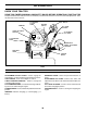
ASSEMBLY HOW TO SET UP YOUR TRACTOR SEAT CHECK BATTERY (See Fig. 2) • • Lift seat pan to raised position and open battery box door. If this battery is put into service after month and year indicated on label (label located between terminals) charge battery for minimum of one hour at 6-10 amps. (See "BATTERY" in CUSTOMER RESPONSIBILITIES section of this manual for charging instructions).
ASSEMBLY 3CHECKLIST TO DRIVE TRACTOR OFF SKID (See Operation section, page 10, for location and function of controls) BEFORE YOU OPERATE AND ENJOY YOUR NEW TRACTOR, WE WISH TO ASSURE THAT YOU RECEIVE THE BEST PERFORMANCE AND SATISFACTION FROM THIS QUALITY PRODUCT. PLEASE REVIEW THE FOLLOWING CHECKLIST: ✓ All assembly instructions have been completed. ✓ No remaining loose parts in carton. ✓ Battery is properly prepared and charged. (Minimum 1 hour at 6 amps).
OPERATION These symbols may appear on your tractor or in literature supplied with the product. Learn and understand their meaning.
OPERATION KNOW YOUR TRACTOR READ THIS OWNER'S MANUAL AND SAFETY RULES BEFORE OPERATING YOUR TRACTOR Compare the illustrations with your tractor to familiarize yourself with the locations of various controls and adjustments. Save this manual for future reference. LIGHT SWITCH ATTACHMENT CLUTCH LEVER IGNITION SWITCH AMMETER THROTTLE/CHOKE CONTROL LIFT LEVER PLUNGER ATTACHMENT LIFT LEVER CLUTCH/BRAKE PEDAL MOWER DECK HEIGHT ADJUSTMENT POSITIONS GEARSHIFT LEVER PARKING BRAKE FIG.
OPERATION The operation of any tractor can result in foreign objects thrown into the eyes, which can result in severe eye damage. Always wear safety glasses or eye shields while operating your tractor or performing any adjustments or repairs. We recommend a wide vision safety mask over spectacles or standard safety glasses. IMPORTANT: LEAVING THE IGNITION SWITCH IN ANY POSITION OTHER THAN "OFF" WILL CAUSE THE BATTERY TO BE DISCHARGED, (DEAD). HOW TO USE YOUR TRACTOR TO SET PARKING BRAKE (See Fig.
OPERATION TO ADJUST GAUGE WHEELS (See Fig. 6) CAUTION: Do not operate the mower without either the entire grass catcher, on mowers so equipped, or the discharge guard in place. Gauge wheels are properly adjusted when they are slightly off the ground when mower is at the desired cutting height in operating position. Gauge wheels then keep the deck in proper position to help prevent scalping in most terrain conditions. • Adjust gauge wheels with tractor on a flat level surface.
OPERATION ADD GASOLINE • COLD WEATHER STARTING ( 50° F and below) • When engine starts, allow engine to run with the throttle control in the choke position until the engine runs roughly, then move throttle control to fast position. This may require an engine warm-up period from several seconds to several minutes, depending on the temperature. • The attachments can also be used during the engine warm-up period.
CUSTOMER RESPONSIBILITIES MAINTENANCE SCHEDULE FILL IN DATES AS YOU COMPLETE REGULAR SERVICE E S S GE RS S US UR OUR OU SON ORA UR O H O H H A 0 ST E 8H SE 25 50 10 RE Y Y Y Y Y RE R R R R R O O E E F E E E F SERVICE EV EV EV EV EV BE BE H AC DATES Check Brake Operation Check Tire Pressure T R A C T 0 R Check Operator Presence and Interlock Systems Check for Loose Fasteners Sharpen/Replace Mower Blades 7 4 Lubrication Chart Check Battery Level 6 Clean Battery and Terminals Check Transaxle Cooling A
CUSTOMER RESPONSIBILITIES TRACTOR MANDREL ASSEMBLY TRAILING EDGE UP Always observe safety rules when performing any maintenance. CENTER HOLE BRAKE OPERATION If tractor requires more than six (6) feet stopping distance at high speed in highest gear, then brake must be adjusted. (See “TO ADJUST BRAKE” in the Service and Adjustments section of this manual). STAR LOCK WASHER TIRES BLADE • Maintain proper air pressure in all tires (See “PRODUCT SPECIFICATIONS” section of this manual).
CUSTOMER RESPONSIBILITIES BATTERY TO CHANGE ENGINE OIL (See Fig. 11 and 12) Determine temperature range expected before oil change. All oil must meet API service classification SF-SJ. • Be sure tractor is on level surface. • Oil will drain more freely when warm. • Catch oil in a suitable container. • Remove oil fill cap/dipstick. Be careful not to allow dirt to enter the engine when changing oil. • Remove cap from bottom fitting of drain valve and install the drain tube onto the fitting.
CUSTOMER RESPONSIBILITIES CLEAN AIR SCREEN (See Fig. 13) AIR FILTER (See Fig. 14) Air screen must be kept free of dirt and chaff to prevent engine damage from overheating. Clean with a wire brush or compressed air to remove dirt and stubborn dried gum fibers. Your engine will not run properly using a dirty air filter. Clean the foam pre-cleaner after every 25 hours of operation or every season. Service paper cartridge every 100 hours of operation or every season, whichever occurs first.
CUSTOMER RESPONSIBILITIES MUFFLER Inspect and replace corroded muffler and spark arrester (if equipped) as it could create a fire hazard and/or damage. CLAMP CLAMP SPARK PLUGS Replace spark plugs at the beginning of each mowing season or after every 100 hours of operation, whichever occurs first. Spark plug type and gap setting are shown in “PRODUCT SPECIFICATIONS” section of this manual. FUEL FILTER FIG. 15 IN-LINE FUEL FILTER (See Fig. 15) The fuel filter should be replaced once each season.
SERVICE AND ADJUSTMENTS CAUTION: BEFORE PERFORMING ANY SERVICE OR ADJUSTMENTS: • Depress clutch/brake pedal fully and set parking brake. • Place gearshift lever in neutral (N) position. • Place attachment clutch in “DISENGAGED” position. • Turn ignition key “OFF” and remove key. • Make sure the blades and all moving parts have completely stopped. • Disconnect spark plug wire from spark plug and place wire where it cannot come in contact with plug. TRACTOR • TO REMOVE MOWER (See Fig.
SERVICE AND ADJUSTMENTS TO LEVEL MOWER HOUSING • Adjust the mower while tractor is parked on level ground or driveway. Make sure tires are properly inflated (See “PRODUCT SPECIFICATIONS” section of this manual). If tires are over or underinflated, you will not properly adjust your mower. • SIDE-TO-SIDE ADJUSTMENT (See Figs. 17 and 18) • Raise mower to its highest position. • At the midpoint of both sides of mower, measure height from bottom edge of mower to ground.
SERVICE AND ADJUSTMENTS TO ADJUST BRAKE (See Fig. 22) TO ADJUST STEERING WHEEL ALIGNMENT Your tractor is equipped with an adjustable brake system which is mounted on the right side of the transaxle. If tractor requires more than six (6) feet stopping distance at high speed in highest gear, then brake must be adjusted. • Depress clutch/brake pedal and engage parking brake. • Measure distance between brake operating arm and nut “A” on brake rod.
SERVICE AND ADJUSTMENTS NEGATIVE TERMINAL POSITIVE TERMINAL KEPS NUT HEX BOLT POSITIVE (RED) CABLE CHASSIS CABLES FIG. 27 NEGATIVE TERMINAL CHARGED BATTERY POSITIVE TERMINAL TO REPLACE HEADLIGHT BULB • • • FIG. 25 • • Connect one end of the BLACK cable to the NEGATIVE (-) terminal of fully charged battery. Connect the other end of the BLACK cable to good CHASSIS GROUND, away from fuel tank and battery.
SERVICE AND ADJUSTMENTS ENGINE PRELIMINARY SETTING • Air cleaner assembly must be assembled to the carburetor when making carburetor adjustments. • Be sure the throttle control cable is adjusted properly (see above). FINAL SETTING • Start engine and allow to warm for five minutes. Make final adjustments with engine running and shift/motion control lever in neutral (N) position. • Move throttle control lever to slow position. With finger, rotate and hold throttle lever against idle speed screw.
STORAGE Immediately prepare your tractor for storage at the end of the season or if the tractor will not be used for 30 days or more. • CAUTION: Never store the tractor with gasoline in the tank inside a building where fumes may reach an open flame or spark. Allow the engine to cool before storing in any enclosure. ENGINE FUEL SYSTEM IMPORTANT: IT IS IMPORTANT TO PREVENT GUM DEPOSITS FROM FORMING IN ESSENTIAL FUEL SYSTEM PARTS SUCH AS CARBURETOR, FUEL FILTER, FUEL HOSE, OR TANK DURING STORAGE.
TROUBLESHOOTING POINTS PROBLEM CAUSE Will not start 1. 2. 3. 4. 5. 6. 7. Out of fuel. Engine not “CHOKED” properly. Engine flooded. Bad spark plug. Dirty air filter. Dirty fuel filter. Water in fuel. 1. 2. 3. 4. 5. 6. 7. 8. 9. Loose or damaged wiring. Carburetor out of adjustment. 8. 9. 10. Hard to start CORRECTION Engine valves out of adjustment. 10. Fill fuel tank. See “TO START ENGINE” in Operation section. Wait several minutes before attempting to start. Replace spark plug.
TROUBLESHOOTING POINTS PROBLEM CAUSE CORRECTION Engine continues to run when operator leaves seat with attachment clutch engaged 1. Faulty operator-safety presence control system. 1. Check wiring, switches and connections. If not corrected, contact an authorized service center/ department. Poor cut - uneven 1. 2. 3. 4. 5. Worn, bent or loose blade. Mower deck not level. Buildup of grass, leaves, and trash under mower. Bent blade mandrel.
REPAIR PARTS TRACTOR - - MODEL NUMBER PO14542B SCHEMATIC RED BLACK BATTERY RED A RED FUSE AMMETER (OPTIONAL) M STARTER BLACK WHITE SOLENOID RED B S G BLACK L M CLUTCH / BRAKE (PEDAL UP) A1 A2 WHITE SEAT SWITCH (NOT OCCUPIED) IGNITION SWITCH WHITE BLACK BLACK BLACK BLACK HOUR METER ATT'MENT CLUTCH (CLUTCH OFF) GROUNDING CONNECTOR (OPTIONAL) BLUE SPARK PLUG GAP (2 PLUGS ON TWIN CYL.
REPAIR PARTS TRACTOR - - MODEL NUMBER PO14542B ELECTRICAL 21 22 42 24 41 43 27 27 40 26 27 27 25 16 16 33 30 D. C.
REPAIR PARTS TRACTOR - - MODEL NUMBER PO14542B ELECTRICAL KEY NO. PART NO.
REPAIR PARTS TRACTOR - - MODEL NUMBER PO14542B CHASSIS AND ENCLOSURES 212 17 30 24 29 18 58 24 12 28 25 26 26 25 53 5 51 52 31 55 5 3 209 57 9 11 208 15 209 209 8 54 209 6 26 1 16 13 3 35 145 37 37 33 10 3 2 35 3 34 38 206 208 26 3 3 38 30
REPAIR PARTS TRACTOR - - MODEL NUMBER PO14542B CHASSIS AND ENCLOSURES KEY NO. PART NO.
REPAIR PARTS TRACTOR - - MODEL NUMBER PO14542B DRIVE 89 51 61 19 42 115 57 19 42 90 31 33 63 43 88 87 52 60 86 81 56 59 83 84 68 42 23 61 82 9 86 85 88 10 13 117 21 8 80 87 6 56 41 26 58 5 40 5 4 55 20 38 26 6 3 85 17 65 26 47 39 11 50 49 52 51 79 61 110 30 111 51 110 19 61 62 27 35 77 37 36 45 46 34 110 54 45 44 48 25 19 28 24 36 2 15 77 96 26 53 74 78 29 76 1 35 75 32 26 22 27
REPAIR PARTS TRACTOR - - MODEL NUMBER PO14542B DRIVE KEY NO. PART NO.
REPAIR PARTS TRACTOR - - MODEL NUMBER PO14542B STEERING ASSEMBLY 38 63 11 39 1 41 42 37 37 36 62 44 51 8 54 17 27 18 68 67 67 19 46 8 23 22 47 6 9 65 46 85 2 11 67 13 8 66 40 7 29 79 85 6 9 9 5 47 80 25 7 3 32 9 5 68 11 82 29 26 4 43 15 40 15 43 29 28 15 10 30 34 6 8
REPAIR PARTS TRACTOR - - MODEL NUMBER PO14542B STEERING ASSEMBLY KEY NO. PART NO.
REPAIR PARTS TRACTOR - - MODEL NUMBER PO14542B ENGINE 3 2 72 62 1 81 13 78 38 32 14 16 44 78 46 33 37 31 33 40 45 29 23 OPTIONAL EQUIPMENT Spark Arrester 36 4
REPAIR PARTS TRACTOR - - MODEL NUMBER PO14542B ENGINE KEY NO. PART NO.
REPAIR PARTS TRACTOR - - MODEL NUMBER PO14542B SEAT ASSEMBLY 1 8 8 9 14 9 7 7 10 5 6 22 21 2 24 5 26 16 25 15 23 4 13 17 3 12 KEY NO. PART NO. DESCRIPTION KEY NO. 1 2 3 4 5 6 7 8 9 10 12 13 140116 140551 71110616 19131610 145006 73800600 124181X 17000616 19131614 174894 121246X 121248X Seat Bracket Pnt Pivot Seat (blk ) Bolt Washer 13/32 x 1 x 10 Ga Clip Push-In Hinged Nut Spring Seat Cprsn 2 250 Blk Zi Screw 3/8-16 x 1.
REPAIR PARTS TRACTOR - - MODEL NUMBER PO14542B DECALS 4 3 2 10 12 12 9 16 1 6 11 20 14 KEY NO. PART NO. DESCRIPTION KEY NO. PART NO.
REPAIR PARTS TRACTOR - - MODEL NUMBER PO14542B MOWER LIFT 7 8 5 1 3 13 2 4 6 6 11 5 4 12 13 19 20 13 15 31 32 13 19 20 17 18 20 16 20 15 31 32 40
REPAIR PARTS TRACTOR - - MODEL NUMBER PO14542B MOWER LIFT KEY NO. PART NO. DESCRIPTION 1 2 3 4 5 6 7 8 11 12 13 15 16 17 18 19 20 31 32 159460 159471 105767X 12000002 19211621 120183X 109413X 124526X 139865 139866 4939M 173288 73350800 130171 73800800 139868 163552 169865 73540600 Wire Asm Inner/Sprg w/Plunger Shaft Asm Lift Pin Groove E Ring #5133-62 Washer 21/32 x 1 x 21 Ga.
REPAIR PARTS TRACTOR - - MODEL NUMBER PO14542B MOWER DECK 68 40 37 36 40 67 157 158 156 153 151 143 155 144 45 150 40 37 159 152 46 153 154 145 44 116 113 111 114 48 54 115 120 117 59 56 53 52 55 51 147 142 49 50 146 33 32 31 30 121 119 148 121 35 118 114 34 21 21 112 115 118 117 119 1 147 2 21 142 120 116 113 21 22 23 24 25 26 2 16 28 15 14 20 18 3 4 18 149 13 5 6 11 19 21 10 9 8 42 29 27
REPAIR PARTS TRACTOR - - MODEL NUMBER PO14542B MOWER DECK KEY NO. PART NO.
SERVICE NOTES 44
LIMITED WARRANTY The Manufacturer warrants to the original consumer purchaser that this product as manufactured is free from defects in materials and workmanship. For a period of two (2) years from date of purchase by the original consumer purchaser, we will repair or replace, at our option, without charge for parts or labor incurred in replacing parts, any part which we find to be defective due to materials or workmanship. This Warranty is subject to the following limitations and exclusions. 1.
SERVICE ® TECUMSEH Issued January 1980 Revised January 1991 POLICY WARRANTY ® TECUMSEH LIMITED WARRANTIES FOR NEW PEERLESS GEAR POWER TRAIN COMPONENTS A.
15° MAX. SIGHT AND HOLD THIS LEVEL WITH SKY LINE OR TREE. CUT OUT ON D THIS OTT IS A ED L 15° S INES LOP E Operate your Tractor up and down the face of slopes (not greater than 15°), never across the face. Make turns gradually to prevent tipping or loss of control. Exercise extreme caution when changing direction on slopes.