
Specifications

Specification
Project Dräger BT Module -
Confidential Information. Property of Dräger Safety AG & Co. KGaA. All
rights reserved.
To be passed on only after written consent by Dräger Safety AG & Co.
KGaA.
Printed versions are uncontrolled
Version: 0.7
State: Draft
18 / 25
5 Maintenance Access Test modes
Both Dräger Moduls can be tested with the Dräger Test board part number 3713475. Either the 17x10mm or
the 9x11mm variant is placeable on this Test board. All available Pins are connected to Test points. The
Dräger BT Modules can be supplied either with an external controlled power supply or with an equipped
DC/DC Boost Buck converter powered with batteries for example. Please refer to dataset 10002090 for further
information.
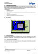
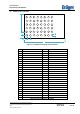
Figure 3.4-1: Dräger Test Board 3713475
Both Modules use separate software interfaces for programming. The 17x10mm relates to Test Points
XP3(SWDIO) and XP4(SWDCLK) and the 9x11mm module use the Tests Points XP1(SWDIO) and
XP2(SWDCLK). The Solder Pads X100 and X200 should be used to connect the Voltage source. The
estimated maximum current is 50mA. The Reset Switches S1 and S2 are just placeholders and so should not
described here.
The LED V1indecates, that the Modules are supplies with their VCC voltage. The LED V2 could be used for
debug purposes by programming an GPIO from the connected module.
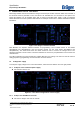
5.1 Setup power supply
To Setup the supply voltage for the connected modules, X600 and X700 shall be set in the right position.
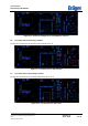
5.1.1 Setup for extern-controlled power supply
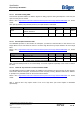
➔ Set X600 and X700 to Vin.
Figure 5.1-1 Test board configured for external supply
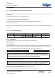
5.1.2 Setup to use Buck/Boost converter
➔ Set X600 to “Regler” and X700 to “VBoost”.