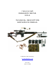
7.62-mm SVD DRAGUNOV SNIPER RIFLE TECHNICAL DESCRIPTION AND SERVICE MANUAL Adapted to PDF format by: hootbro@angelfire.com Rev 1.
CONTENTS Introduction -------------------------------------------------- 3 1. Technical Description -------------------------------------- 3 1.1. Purpose of rifle ----------------------------------------- 3 1.2. Technical data ------------------------------------------- 4 1.3. Rifle components ----------------------------------------- 5 1.4. Design and operation of rifle ---------------------------- 6 1.5. Design and operation of sight and its component parts ---- 9 1.6.
INTRODUCTION Technical Description and Service Manual of the 7. 62-mm Dragunov sniper rifle (SVD) is intended for studying the rifles and optical sights and keeping them in constant fighting ready for action. This paper includes specifications and data of the rifle and optical sight design and operation, as well as main rules necessary to provide for the proper maintenance of the rifle with the sight and full using of their technical capabilities.
1.1.2. The sniper rifle uses rifle cartridges with ordinary, tracer and armor-piercing-incendiary bullets or rifle sniper cartridges. The fire is delivered in single shots. 1.1.3. The optical sight permits to conduct night firing at infrared sources and under bad conditions of illumination, when it is difficult to fire at targets with the open sight.
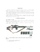
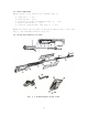
1.3. Rifle components 1.3.1. The set of the sniper rifle includes (Fig. 1): • • • • • sight PSO-1 - 1 pc.; knife bayonet - 1 pc.; carrier for a sight and magazines (Fig. 3) - 1 pc.; bag for SPTA (Fig. 4) - 1 pc.; sling for carrying small arms (Fig. 5) - 1 pc.; 1.3.2. The sniper optical sight is delivered complete with a slip cover (Fig. 6) and individual SPTA set (Fig. 11). 1.4. Design and operation of rifle Fig. 2. 7.
Fig. 2. 7.62-mm Dragunov sniper rifle continued: 1 - bolt support; 2 - firing pin; 3 - cover; 4- guiding rod; 5 guiding bushing; 6 - bolt; 7 - extractor pin; 8 - firing pin stud; 9 extractor spring; 10 - extractor; 11 - return spring; 12 - sight leaf slide; 13 - sight leaf; 14 - hand guard, L.H.
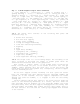
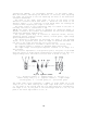
Fig. 3. Carrier for optical sight and magazines. Fig. 4. Bag for SPTA.
Fig. 5. Sling for carrying small arms. Fig. 6. Slip cover for sight. To fire a shot, it is necessary to release the trigger and press it anew. After the trigger has been released, the rod moves forward and its hook engages the sear and, if pressed, the rod hook turns the sear and disengages it from the hammer-cocking cam. The hammer actuated by the mainspring turns round its pin and strikes the firing pin. The latter travels forward and impinges the primer. Thus, a shot is fired.
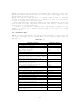
1.5. Design and operation of sight and its component parts 1.5.1. The sniper optical following main parts: • • • • • • • • • • • • • sight PSO-1 (Fig. 7) consists of the body; objective; eyepiece; blind; eye shield; knob with the scale of sight angles; knob with the scale of deflection corrections; handle; colored glass; guide; supply source; lamp; cap. The objective in a mount with a collapsible blind is screwed into the body.
Inscriptions "BnpaBo - To the Right", "BJieBo - To the Left", "CTn MPI" and arrows, indicating the direction of rotation, when adjusting the sight are plotted on the nut fastening the knob of the deflection correction mechanism. The band of the sight angle knob, as well as the band of the deflection correction knob each bears 60 divisions. The value of one division equals 0-00.5. Divisions on knob bands serve for reading the correction when adjusting the sight on the rifle.
Fig. 9. Field of vision view: Plotted to the left and to the right from the angle marks is the scale of deflection corrections. The value of each division is 0-01. The values of deflection corrections 0-05 and 0-10 are marked out by an elongated dash line. The value of deflection correction 0-10 is marked out by an elongated dash line and designated by a digit 10. Two horizontal dash lines are plotted from the right and from the left of the deflection correction scale.
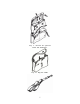
THE SCOURER is used for cleaning and lubricating the barrel bore as well as the passages and cavities of other rifle parts. THE BRISTLE BRUSH is intended for cleaning the barrel bore with the RCHS solution. THE SCREWDRIVER is used in disassembling, assembling the rifle and in cleaning the gas chamber and the gas tube. It is also used as a wrench to adjust the front sight position in height. THE DRIFT is used for driving the pins and studs out.
Fig. 11. Sight PSO-1 with individual SPTA set: 1 - wrench; 2 - sections of mercury-zinc cells 2RC63; 3 colored glass; 4 - lamps CM 2.5-0.075 (in cassette); 5 cap; 6 - illuminating system The illuminating system is intended for lighting the reticle when working with the sight at the environmental temperature below 0 grad. Ñ. The wrench serves for screwing the reticle-illuminating lamp in and out. The napkin is intended for cleaning optical parts. Supply source, lamps and a cap are delivered as spare parts.
2. SERVICE MANUAL 2.1. General The sniper rifle and optical sight should be kept in good repair and in a ready-for use condition, which can be obtained by timely and skilful cleaning and lubricating, careful handling, proper storage, timely technical inspection and remedying of the troubles. 2.2. Safety precautions 2.2.1. To carry out training in disassembly and assembly of the rifle use blank rifles only.
2.4. Zeroing of rifle and procedure of optical sight operation 2.4.1. The sniper rifle being in the service of a subunit should be zeroed. The necessity of rifle zeroing is determined by test firing. Rifles are subjected to test firing: a) on reception of the rifle by the subunit; b) after the rifle parts repair or replacement, which may affect the rifle fire accuracy; c) in case of excessive deviation of the mean point of impact (MPI), or bullet dispersion, which does not meet the accuracy requirements.
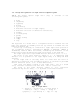
Fig. 12. Determination of mean point of impact (MPI): 1 - by consequent division of lines; 2 - with symmetrical arrangement of hits. CTn means MPI Repeat test-firing to make sure that the above displacement of the front sight and its body is properly done. After the sniper rifle has been zeroed, remove the old notch and make a new notch on the front-sight body. 2.4.4. To zero the rifle with the optical sight attach it to the rifle and put the cheek plate on the butt.
Sight angles and deflection correction angles are set in this case by counting clicks of the retainer from zero position. Bear in mind that the fixation of the sight angle knob is performed from "0" to "3" every whole division, i.e. every 100 m and further on till setting 10 every half-division i.e. every 50 m. The fixation of the knob of deflection corrections is effected every half division, i.e. every 000.5. 2.4.7.
Release safety lock and press the trigger; a click should be heard, which is indicative of the energetic blow delivered by the hammer against the firing pin. Set the rifle at safe again and attach the magazine; the bolt support should not move backward, the safety lock should be reliably retained in the required position. Check the feed of cartridges into the cartridge chamber, extraction and ejection of fired cases (cartridges).
Trouble Cartridge not fed into chamber. Bolt in front position, but no shot fired (no cartridge in cartridge chamber) Table No. 2 Cause Dirty or faulty magazine. Faulty magazine latch Misalignment of cartridge. Cartridge with its bullet rests on barrel breech face, moving parts stop in middle position Bent guiding lugs of magazine side walls Misfire. Bolt in front position, cartridge in cartridge chamber, hammer released, no shot fired Faulty cartridge.
Trouble Fired case stuck or fails to be ejected. Fired case is not ejected from receiver, it is in the receiver, in front of bolt or rammed by the bolt into cartridge chamber again Table No. 2 continued: Cause Dirty friction parts, gas passages or cartridge chamber Dirty or faulty extractor Remedy Retract the bolt support reloading handle, remove the fired case and proceed with firing. If the stoppage is repeated, clean the gas passages, the friction parts and the cartridge chamber.
g. Detach the firing and trigger mechanism. Turn the safety lever upward till it occupies the vertical position, shift it to the right and detach from the receiver; holding the trigger guard move the firing and trigger mechanism downward to detach it from the receiver. h. Detach the hand guards.
i. Connect the magazine. Insert the front hook of magazine into the opening of the receiver and turn the magazine to yourself to let the latch engage the rear hook of the magazine. 2.6.4. To completely disassemble the sniper rifle, proceed as follows: a. Perform the partial disassembly as instructed in item 2.6.2. b. Disassemble the magazine.
d. Assemble the retracting mechanism.
2.7. Cleaning and lubrication 2.7.1. The rifle should be cleaned in the following cases: a. when preparing the rifle for firing; b. after firing with live and blank ammunition, immediately after finishing the fire; c. after guard duty or field exercises without firing, just on return to the barracks; d. in combat situation and prolonged tactical exercises, daily during lulls of the fight and during the intervals in the exercises; e. if the sniper rifle is not in use, at least once a week. 2.7.2.
scourer with the tow forward along the entire length of the barrel bore several times. Remove the cleaning rod, change the tow, soak it in liquid rifle oil and, adhering to the above procedure, scour the bore several times. Then thoroughly wipe the barrel bore with the clean dry tow, then with a clean waste cloth. To clean the barrel bore with the Ð×Ñ solution, use the brush soaked in the solution; then wipe the barrel bore with tow.
carried with one magazine attached. The rest magazines are in the carrier. 2.8.5. When traveling by trucks or armored personnel carriers hold the rifle between the knees, in the vertical position, and when traveling by tanks hold the rifle with the hands, taking care to protect from striking against the armor. 2.8.6. When transported by railway or by water, place the rifle on a special arm rack.
Authors Notes: I have adapted this manual from resources obtained at http://kalashnikov.guns.ru/manual/english/svd/1.html I have attempted to correct most grammatical errors that were in the original document. I assume this to be non-copyright material. I offer this freely to anyone who wishes to use this for personal purposes. Any comments or suggestion to improve this document. Please forward to: hootbro@angelfire.