
Manual
21
g. Detach the firing and trigger mechanism. Turn the safety lever
upward till it occupies the vertical position, shift it to the right
and detach from the receiver; holding the trigger guard move the firing
and trigger mechanism downward to detach it from the receiver.
h. Detach the hand guards. Press the axle pin of the upper band to
the gas tube so that the lug of the axle pin tongue comes out of the
band recess and turn the latch clockwise as far as it will go: shift
the upper band to the muzzle part; pressing the hand guard downward and
shifting it sideways, detach it from the barrel.
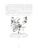
i. Detach the gas piston and the pusher together with the spring.
Pull the pusher backward, disengage its front end from the gas piston
port and detach the piston from the gas tube; insert the front end of
the pusher into the gas tube and compress the pusher spring till it
protrudes beyond the passage of the sight bar; detach the pusher and
the spring, then detach the spring from the pusher.
2.6.3. To assemble the sniper rifle after partial disassembly, adhere
to the following procedure;
a. Connect the gas piston and the pusher with the spring. Fit the
spring onto the rear end of the pusher; insert the front end of the
pusher into the gas tube, compress the spring and insert the rear end
of the pusher together with the spring into the passage of the sight
bar; pull the pusher backward and remove its front end from the gas
tube sideways; insert the gas piston into the gas tube, and the front
end of the pusher into the piston socket.
b. Connect the hand guards. Insert the rear end of the right (left)
hand guard into the lower band, press the hand guard downward and
fasten it on lugs of the supporting ring; fit the upper band onto the
end pieces of the hand guards and turn the axle pin of the upper band
to the gas tube so as to let its lug enter the recess on the band.
c. Connect the firing and trigger mechanism. Engage the recesses of
the firing and trigger mechanism body with the stop pin and press the
firing and trigger mechanism to the receiver; insert the safety lever
pin into the hole of the receiver, then turn the safety lever in the
clockwise direction so as to let the lug of the safety lever enter the
lower recess of the receiver.
d. Connect the bolt to the bolt support, insert the bolt into the
passage of the bolt support, turn the bolt so that its driving lug
enters the shaped recess of the bolt support and move the bolt forward
as far as it will go.
e. Connect the bolt support and the bolt. Insert the guiding lugs of
the bolt support into recesses of the receiver and move the bolt
support forward.
f. Connect the receiver cover together with the retracting
mechanism. Insert the return spring into the passage of the bolt
support, insert the lugs on the front end of the cover into recesses on
the lower band; press the rear end of the cover to make the cover fit
tightly to the receiver, turn the axle pin of the receiver cover
forward to set it on the cheek plate limiter.
g. Connect the butt cheek plate. Put the cheek plate on the butt
with its fastener to the right, fit the loop onto the hook of the clip
and turn fastener upward,
h. Connect the optical sight. Match the slots on the sight bracket
with the lugs on the left wall of the receiver; shift the sight forward
as far as it will go and turn the handle of the clamping screw towards
the objective so as to let the handle lug enter the recess of the
bracket.