
User manual


8
Superior Broadcast
ATVCA Amplifier User Manual
Superior Broadcast ATVCA Amplier
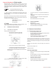
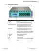
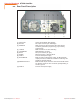
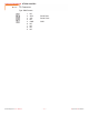
4.4 Rear Panel Description
[1] AIR FLOW Grill for the ventilation ow passage
[2] RF OUT RF output connector (7/8” EIA ange)
[3] SERVICE DB9 connector for interconnection with other devices
and factory parameters programming (only for factory
programming).
[4] I
2
C BUS DB9 connector for I
2
C bus networking
[5] TELEMETRY DB25 telemetry connector
[6] RF IN RF input connector (“N” type)
[7] MAINS Mains supply plug, 1230V 50-60 Hz
[8] FUSE 1 Fuse for mains power supply.
[9] RF MONITOR BNC connector for RF monitor output, -60 dB wrt the RF
output power level, suitable for modulation monitoring. Not
suitable for spectral analysis.
[10] INTERLOCK OUT BNC interlock output connector: when the transmitter enters
into stand-by mode, the inner conductor, tipically oating, is
forced to ground.
[11] FUSE 2 Fuse for mains power supply.
6 / 32
User Manual
Rev. 1.0 - 22/11/10
ATVCA