
Instruction manual

12 Setup and Programming (Continued) / Operation
INTERLEAVER: Sets the QAM modulator interleaver. Choose
among the available selections based upon your system / set top
box requirements. For typical 256-QAM. DigiCipher II CATV
systems, I128, J1 is the most commonly used interleave setting but
many other choices are available. This menu does not appear in
the adjust mode if the QAM mode is A (DVB) as there is only one
choice in the DVB standard. When not in adjust mode, this screen
will display the setting in QAM - A modes as well.
OUTPUT FORMAT: For normal operation, select NORMAL. For
system level set up, choose CW to provide a CW carrier at the
center frequency of the output channel for use in leveling a system
when a QAM power meter is not available. To disable all RF output,
select STANDBY. In the CW mode, the CW carrier can be
measured on a spectrum analyzer without a need to apply a
bandwidth correction or it can be measured with an analog meter
tuned to channel center. The CW power measured will equal the
channel QAM power when the modulator is returned to NORMAL
output mode. Usually QAM signals are set 5 dB to 10 dB
below analog NTSC channels when balancing a system. The
PRBS modes provide a pseudo random binary sequence output
test signal for use in laboratory testing.
OUTPUT CHANMAP, OUTPUT CHANNEL: Select the desired EIA
CATV channel output using these two menus.
RF OUT: Select the desired RF output signal level. The available
range is between 45 dBmV and 62 dBmV, selectable in 0.5 dB
steps. The output accuracy is ± 1 dB.
SETUP: SDE24
SELECT: The LEFT and RIGHT buttons allow the user to scroll
through the encoder numbers for each encoder installed in the
MEQ1000A as well as the MEQ1000A itself. Use the LEFT and
RIGHT buttons to select the encoder to be programmed.
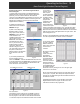
OPERATION - MULTIPLEXING TWO ATSC INPUTS
To use the DTD1000, SDE24 and/or the ASII modules to multiplex
two ATSC inputs, proceed as follows:
1) Connect the off-air antenna, CATV feed, or audio and video
(SDE24) or ASI feed, to the INPUT A and INPUT B inputs of the
MEQ1000A. If using two RF inputs the two input connectors are
available in case the two RF signals must come from different
antennas or if one signal is coming from a cable system, etc. If
using a common antenna, use a good quality two way splitter to
split the antenna and feed each input.
2) Plug the power cord from the unit into the power source.
3) Follow the instructions in the programming section above to
set the channel map and channel number for both INPUT
MODULE A and INPUT MODULE B.
4) Set the QAM SYMRATE to PRESET.
5) Set the MULTIPLEX setting ENABLED
6) Set the INPUT B OFFSET to 10. Read details in programming
section to determine if you need another value.
7) Select the desired MPEG programs. (See the previous
section for details.)
8) In the PSIP menu, select BASIC MGT VCT for now, this may
be changed later. See programming section for detail.
9) In the VCT TABLE menu, select TVCT.
10) In the MAJOR CHANNEL menu, select OUTPUT CHANNEL.
This may be changed later.
11) From the QAM MODE menu, set the QAM modulator to
QAM-256B for use in a DigiCipher II environment. If DVB, use
QAM-256A instead.
12) In the QAM SYMRATE menu, select PRESET.
13) Set the INTERLEAVER to I128,J1 if in a DigiCipher II
environment. There is no interleaver menu when the QAM
mode is set to A (DVB).
14) Set the OUTPUT FORMAT to NORMAL.
15) Set the OUTPUT CHANMAP and OUTPUT CHANNEL to
the desired EIA CATV output channel.
If the second program is being input to a ASII Module via the ASI
input instead of a DTD1000, the same steps apply except that
there will be no parameters to set for the ASII MODULE.
SET TOP BOX MAPPING
When setting up a program map for your set top boxes to include
off-air channels that are multiplexed by the MEQ1000A be sure to
inform the programmer that the MPEG program numbers for the
programs coming in through INPUT MODULE B or ASI B have
been offset by the amount selected in the INPUT B OFFSET
menu. As an example: If input A is providing a channel with
MPEG programs 1 and 2 in the stream and input B is providing a
channel with MPEG programs 1, 2, 3, 4, and 5 in the stream, and
the INPUT B OFFSET is set to 10, then the new output signal will
contain MPEG programs with program numbers of 1, 2, 11, 12,
13, 14, and 15. If the set top is not looking for the right program
number, you will not receive any video!
VIDEO: This menu entry allows the user to select between SVIDEO
and COMPOSITE video input for each selected encoder.
FORMAT: Either MPEG2 or MPEG4 H.264 may be selected as the
output format for the selected encoder using this menu item.
Encoder 2 on a given SDE24 has no option. It is forced to MPEG2.
RESOLUTION: The resolution of the video output of each encoder
may be selected from this menu item. The choices range from 720
x 480 thru 353 x 240 as shown on the software flow chart on page
9.
BRIGHTNESS, CONTRAST, SATURATION and HUE: These
menu items allow the user to assign each of these parameters of
the output video values from 0 to 255.
MAX AUDIO IN: This menu entry allows the user to set the
maximum audio input which may be input to the selected encoder.
The choices are 1 Vrms or 2 V rms.
AUDIO GAIN: The audio output level can be chosen from this
menu item by selection of the appropriate gain. The values range
from + 15 dB to - 15 dB. Audio output can also be completely
eliminated using the ‘MUTE’ selection.
AUDIO ENCODER: The SDE24 includes audio encoders for Dolby
Digital Stereo commercial encoding (AC3) or MPEG1 Layer 2 audio
encoding (MP2). In the USA, the majority of applications will use
AC3 but if your network is using Annex A (DVB) set top boxes, they
may require the MPEG audio selection. Some TVs and set top
boxes will decode either mode but be sure to set the encoder to the
mode used by other programming on your system to insure
complete compatibility. The AUDIO ENCODE(R) menu allows you
to select either AC3 or MP2. Use the up/dn arrow keys to toggle
between the two settings.