MM806 NTSC Modulation Monitor Instruction Manual ® is a registered trademark of the R.L. Drake Company © Copyright 2002 R.L. Drake Company P/N:3852398B-3-200 Printed in the U.S.A.
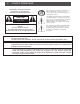
Caution Statements WARNING: TO PREVENT FIRE OR ELECTRICAL SHOCK DO NOT EXPOSE TO RAIN OR MOISTURE A product and cart combination should be moved with care. Quick stops, excessive force and uneven surfaces may cause the product and cart combination to overturn.
Important Safety Instructions 1. Read Instructions—All the safety and operating instructions should be read before the product is operated. 2. Retain Instructions—The safety and operating instructions should be retained for future reference. 3. Heed Warnings—All warnings on the product and in the operating instructions should be adhered to. 4. Follow Instructions—All operating and use instructions should be followed. 5. Cleaning—Unplug this product from the wall outlet before cleaning.
Table of Contents / Description 2 Caution Statements 3 Important Safety Instructions 4 Table of Contents / Description 5 Specifications 6 Front Panel Controls and Indicators 7 Rear Panel Controls and Connections 8 Installation 9 Reference Chart of Off-Air and CATV Channels 10 Service / If You Need To Call For Help 11 Warranty MM806 MODULATION MONITOR MODE POWER CHANNEL CATV BCTV 2 5 VIDEO AUDIO % MODULATION % MODULATION 0 20 40 60 80 100 0 20 40 60 80 100 CATV +100 DEPTH
Specifications RF Input Frequency: 54 - 806 MHz, Off-Air: Channels 2 - 69. CATV: Channels 2 - 125. Input Level: -10 to +35 dBmV. Noise Figure: VHF: 8 dB. UHF: 10 dB. Image Rejection: VHF: 65 dB. UHF: 50 dB. Input Impedance: 75 Ohms. VIDEO Output Level: 1.0 Vp-p nominal, NTSC standard negative sync. Output Impedance: 75 Ohms. Differential Gain: Less than 5%. Differential Phase: Less than 5 degrees. L/C Delay: 125 nSec nominal. AUDIO Output Level: 300 mV rms nominal, unbalanced.
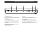
Front Panel Controls and Indicators F1 F2 F3 F4 F5 MM806 MODULATION MONITOR MODE POWER CHANNEL CATV BCTV 2 5 VIDEO AUDIO % MODULATION % MODULATION 0 20 40 60 80 100 0 20 40 60 80 100 CATV +100 DEPTH OF MODULATION 100% = 25 kHz PEAK Figure 1 F1 - POWER Indicator Lights when the unit is connected to the required source of AC power. F2 - Mode Switch Sets the type of channel, Off-Air or CATV. The third position sets a leading “1” for CATV channels from 100 through 125.
Rear Panel Controls and Connections R1 R2 R3 R4 7 R5 CAUTION: - RISK OF FIRE -REPLACE FUSE AS MARKED AFTER DISCONNECTING UNIT FROM AC LINE ATTENTION: - RISQUE D'INCENDIE REMPLACEZ FUSIBLE DU TYPE INDIQUE APRES DEBRANCHER DU SECTEUR Figure 2 R1 - RF INPUT Connector This is the 75 Ohm input to the demodulator circuits from an off-air television receiving antenna or from a CATV cable input. R2 - VIDEO OUTPUT Connector This is the 75 Ohm baseband video output at a nominal 1.
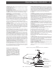
Installation TYPICAL HEADEND MONITOR APPLICATION Choose a Tap value so the video carrier level to the MM806 is in the 0 dBmV to +15 dBmV range. RACK MOUNTING Adequate ventilation is very important in multichannel installations. Units should be spaced apart by at least one panel height wherever possible, and some air movement is advisable in enclosed rack cabinets. Excessive heat will shorten component life and system performance will be degraded without proper cooling.
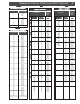
Reference Chart of Off-Air and CATV Channels OFF-AIR CATV VHF BROADCAST CHANNELS Channel Number Visual Carrier Frequency (MHz) 2 3 4 5 6 7 8 9 10 11 12 13 55.25 61.25 67.25 77.25 83.25 175.25 181.25 187.25 193.25 199.25 205.25 211.25 B A N D L O W OFF-AIR UHF BROADCAST CHANNELS Channel Number Visual Carrier Frequency (MHz) 14 15 16 17 18 19 20 21 22 23 24 25 26 27 28 29 30 31 32 33 34 35 36 37 38 39 40 41 42 43 44 45 46 47 48 49 50 51 52 53 54 55 56 57 58 59 60 61 62 63 64 65 66 67 68 69 471.
Service / If You Need To Call For Help SERVICE INFORMATION You may contact the R.L. DRAKE Service Department for additional information or assistance by calling +1 (937) 746-6990, Monday through Friday, between 8:00 A.M. and 4:00 P.M. Eastern Time, except on holidays. You may also contact the R.L. DRAKE Service Department by E-mail at the following address: service@rldrake.com or by Telefax: +1 (937) 743-4576.
Warranty 11 Warranty Three Year Limited Warranty R.L.DRAKE COMPANY warrants to the original purchaser this product shall be free from defects in material or workmanship for three (3) years from the date of original purchase. During the warranty period the R.L.DRAKE COMPANY or an authorized Drake service facility will provide, free of charge, both parts and labor necessary to correct defects in material and workmanship. At its option, R. L. DRAKE Company may replace a defective unit.
R.L. Drake Company 230 Industrial Drive Franklin, Ohio 45005 U.S.A. Customer Service and Parts Telephone: +1 (937) 746-6990 Telefax: +1 (937) 743-4576 World Wide Web Site: http://www.rldrake.
MM806 Modulation Monitor Specifications Sheet For: Direct A/V Inc. MM806 MODULATION MONITOR MODE POWER CHANNEL CATV BCTV 2 5 VIDEO AUDIO % MODULATION % MODULATION 0 20 40 60 80 100 0 20 40 60 80 100 CATV +100 DEPTH OF MODULATION 100% = 25 kHz PEAK RF Input Frequency: 54 - 806 MHz, Off-Air: Channels 2 - 69. CATV: Channels 2 - 125. Input Level: -10 to +35 dBmV. Noise Figure: VHF: 8 dB; UHF: 10 dB. Image Rejection: VHF: 65 dB; UHF: 50 dB. Input Impedance: 75 Ohms.