
Instruction manual


CAUTION:
- RISK
OF FIRE -REPLACE
FUSE AS MARKED
AFTER DISCONNECTING
UNIT FROM AC LINE
ATTENTION:
- RISQUE D'INCENDIE -
REMPLACEZ FUSIBLE DU
TYPE INDIQUE APRES
DEBRANCHER DU SECTEUR
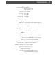
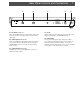
Rear Panel Controls and Connections 7
R1 R2 R3 R4 R5
Figure 2
R4
- FUSE
Always replace this fuse with one of the same type and
rating: 1/8 Amp, 250 V, SLO-BLO®, 3AG type.
R5
- LINE CORD
This is a three-wire power cable. When the cable is
connected to a properly wired AC power line outlet, this
cable grounds the instrument cabinet. Connect to a
nominal 115 VAC ±10%, 60 Hz source. Do not defeat the
safety purpose of the attached line cord plug.
R1
- RF INPUT Connector
This is the 75 Ohm input to the demodulator circuits from
an off-air television receiving antenna or from a CATV
cable input.
R2
- VIDEO OUTPUT Connector
This is the 75 Ohm baseband video output at a nominal
1.0 Vp-p level which is adjustable with the front panel
VIDEO LEVEL control over a range of approximately
0.7 to 1.5 Vp-p.
R3
- AUDIO OUTPUT Connector
The RCA phono connector AUDIO OUT, provides an
unbalanced audio output.