SRR60 Sound Reinforcement Receiver Users’ Manual TM is a registered trademark of R.L. Drake LLC © Copyright 2007 R.L. Drake LLC P/N 3853203A-2007 Printed in U.S.A.
Caution Statements WARNING: TO PREVENT FIRE OR ELECTRICAL SHOCK DO NOT EXPOSE TO RAIN OR MOISTURE A product and cart combination should be moved with care. Quick stops, excessive force and uneven surfaces may cause the product and cart combination to overturn.
Important Safety Instructions 3 14. Outdoor Antenna Grounding—If an outside antenna or cable system is connected to the product, be sure the antenna or cable system is grounded so as to provide some protection against voltage surges and built-up static charges.
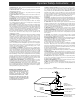
Table of Contents / Specifications TABLE OF CONTENTS 2 3 4 5 6 7 8 9 Caution Statements Important Safety Instructions Table of Contents / Specifications Purpose General Description & Installation Additional System Components Front Panel Controls & Connections Rear Panel Controls & Connections 10 11 12 13 16 17 18 19 BP60 Belt Pack Controls & Connections HHM60 Microphone Controls & Connections Battery installation & Charging Daily Operation General Usage Tips Troubleshooting Guide Service / If you Nee
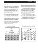
Purpose PURPOSE In a typical classroom environment, a teacher in front of the room lectures to a room filled with 30 or 40 students. Those students in the first few rows can easily hear what the teacher is saying, but those further back in the classroom frequently find that hearing the teacher over the ambient noise of the room can be considerably more difficult. This frequently leads to lack of comprehension, inattention, disorder, teacher fatigue, and a generally less than ideal learning environment.
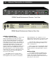
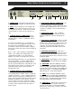
General Description & Installation SRR60 Sound Reinforcement Receiver Front View SRR60 Sound Reinforcement Receiver Rear View GENERAL DESCRIPTION The R.L. Drake model SRR60 is a professional quality Sound Reinforcement Receiver which accepts audio modulated infrared (IR) signals from up to two separate IR transmitters, such as hand held and/or lavaliere microphones.
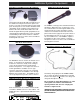
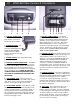
Additional System Components BP60 Belt Pack & EM60 Lavaliere Mic/IR Emitter The lavaliere microphone/IR emitter should be worn at the collarbone level by the instructor. It captures the wearer’s voice and sends it to the battery powered belt pack. The belt pack uses the audio to modulate an RF signal which, in turn, modulates an IR emitter in the lavaliere unit. Thus, the IR emotter bathes the room with the IR signal which is picked up by IR60 sensors strategically placed throughout the room.
1 Front Panel Controls & Connections 2 3 4 5 6 7 8 1. CHANNEL A VOLUME - This control varies the volume of audio on the “A” channel relative to audio on the other audio input channels. The SRR60 “A” channel receives a microphone set to CH 1. 2. CHANNEL A SIGNAL INDICATOR - This green LED lights when a signal is being received from the microphone set for channel 1. 3.
Rear Panel Controls & Connections 1 2 3 1. POWER CORD - The power cord connects the SRR60 Receiver to standard 120 VAC 60 Hz power. 2. FUSE - The fuse holder is in series with the AC power line. If fuse replacement is necessary, use a 1.6 amp 250 V slo-blo fuse. Rotate the fuse holder counterclockwise to remove the fuse when necessary. 3. SPEAKER OUTPUT CONNECTIONS - The speaker output connector consists of 8 screw type terminals, with a “+ “and a “-” terminal for each of four speakers.
BP60 Belt Pack Controls & Connections 1 2 3 4 1. EMITTER CONNECTOR The Lavaliere Mic/IR Emitter plugs into this connector as shown in the photo at right. 2. POWER ON LIGHT - This LED is illuminated green whenever charged batteries are installed and the POWER switch is turned on. When batteries are low, the color will change to red. 3. POWER SWITCH - This switch turns battery power on and off. 4.
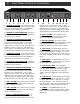
HHM60 Microphone Controls & Connections 1 2 3 4 5 6 1. INFRARED TRANSMITTERS - The HHM60 has two locations for the IR transmitters. One at the bottom of the microphone and one near the top. It is important to keep one of these areas uncovered when the microphone is in use so that the IR signals will reach the sensor. 2. BATTERY CHARGING CONNECTOR - This connector is located on the bottom of the unit.
Battery Installation & Charging Battery Preparation (batteries from retail source) For both the HHM60 Hand Held Microphone, and the BP60 Belt Pack, it will be necessary to remove approximately 1/2 inch of insulation from the negative end of one of the two batteries which will be installed in each unit. This must be done so that the CHARGE CONTACTs will make contact with them. This is shown in the following photo.
Daily Operation BP60 Belt Pack & Lavaliere Mic/IR Emitter 1. Position the Lavaliere microphone/IR emitter at the clavicle (collar bone) level either by clipping onto the instructor’s clothing, or by using the supplied lavaliere lanyard. It is important that the openings in the unit are facing outward so that IR signals will not be blocked. See Photo below. 13 Speaker Output Level Controls 2. Preset the MASTER VOLUME to approximately 60% of its rotation. (About 1:00 o’clock.) 3.
Daily Operation (continued) INDIVIDUAL SPEAKER LEVELS If one area of the room has too much volume and/or microphone feedback, use the indivual speaker level adjustments (rear panel recessed) to reduce the appropriate speaker. Always start with all speaker outputs at max level (full CW viewing rear panel). RCA Phono Connectors TV RECEIVER CHANNEL B 1. Turn off the BP60 Belt Pack, and turn on the HHM60 Hand Held Microphone. Its POWER LED should light.
Daily Operation (continued) AUX OUTPUT The AUX output connectors on the front and rear panels, provide two independent audio outputs which may be used to drive such audio devices as cassette recorders, computers, or assistive listening transmitters. 1. Connect the audio devices to the front panel and rear panel AUX OUTPUT LINE OUT connectors using patch cables with 3.5 mm Audio connectors as shown in the following illustrations. 3.
Daily Operation (cont) & General Usage Tips When audio from the PA system stops, the SRR60 will unmute with a delay time which is determined by the setting of the HOLD TIME control. The further clockwise the control is turned, the longer the time will be between the time the external audio stops and the SSR60 unmutes. The approximate delay time will range from 1 second with the control fully CCW to 15 seconds with the control fully CW.
Troubleshooting Guide CAUSE PROBLEM Receiver won’t turn on. No signal reception. Channel A and/or B signal indicator LED on receiver not lit. Weak or no speaker output. Dead spots in classroom. Acoustic feedback (howling or screeching). 17 CURE Power cord not plugged in. Plug in power cord. Fuse blown Replace with 1.6 250V Amp Slo-Blo. BP60 Belt Pack and/or HHM60 Microphones not turned on. Turn on BP60 and/or HHM60 microphone. BP60 Belt Pack and/or HHM60 batteries are discharged.
Service / If You Need To Call For Help SERVICE INFORMATION You may contact the R.L. DRAKE Service Department for additional information or assistance by calling +1 (937) 746-6990, Monday through Friday, between 8:00 A.M. and 4:00 P.M. Eastern Time, except on holidays. You may also contact the R.L. DRAKE Service Department by E-mail at the following address: TechSupport@rldrake.com or by Telefax: +1 (937) 806-1576.
Warranty 19 Three Year Limited Warranty R.L. DRAKE LLC warrants to the original purchaser this product shall be free from defects in material or workmanship for three (3) years from the date of original purchase. During the warranty period R.L. DRAKE LLC or an authorized Drake service facility will provide, free of charge, both parts and labor necessary to correct defects in material and workmanship. At its option, R.L. DRAKE LLC may replace a defective unit.
R.L. Drake LLC 230 Industrial Drive Franklin, Ohio 45005 U.S.A. Customer Service and Parts Telephone: +1 (937) 746-6990 Telefax: +1 (937) 806-1576 World Wide Web Site: http://www.rldrake.