VM2050 Commercial T Channel Video Modulator (For use in NTSC systems) Instruction Manual ® is a registered trademark of the R.L. Drake Company © Copyright 2002 R.L. Drake Company P/N: 3852412C-2-2002 Printed in U.S.A.
Caution Statements WARNING: TO PREVENT FIRE OR ELECTRICAL SHOCK DO NOT EXPOSE TO RAIN OR MOISTURE A product and cart combination should be moved with care. Quick stops, excessive force and uneven surfaces may cause the product and cart combination to overturn.
Important Safety Instructions, continued 1. Read Instructions—All the safety and operating instructions should be read before the product is operated. 2. Retain Instructions—The safety and operating instructions should be retained for future reference. 3. Heed Warnings—All warnings on the product and in the operating instructions should be adhered to. 4. Follow Instructions—All operating and use instructions should be followed. 5. Cleaning—Unplug this product from the wall outlet before cleaning.
Table of Contents / Description 2 Caution Statements 3 Important Safety Instructions 4 Table of Contents / Description 5 Specifications 6 Front Panel Controls and Indicators 7 Rear Panel Connections 8 Installation 8 Channel Assignments 10 Service / If You Need To Call For Help 11 Warranty VM2050 T CHANNEL MODULATOR VIDEO L EV E L R F O UT P UT AUDIO L EV E L A/V RATIO LEVEL TPOWER MODULATION MODULATION 1 4 CHANNEL OUTPUT ENABLED DESCRIPTION The R.L.
Specifications RF Frequency Range: T Channels T7 - T14, (5.75 - 53.75 MHz). Output Level: +60 dBmV, (adjustable +50 to +60 dBmV). Output Impedance: 75 Ohms. A/V Ratio: Audio carrier -20 to -10 dB referenced to video carrier, adjustable. Frequency Stability: ± 10 PPM. Intercarrier Frequency: 4.5 MHz ± 10 PPM. Spurious Outputs: -60 dBc typical; -58 dBc minimum, measured at -15 dB A/V ratio and with modulator output level of +60 dBmV. In-Channel C/N: 65 dB typical.
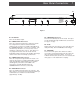
Front Panel Controls and Indicators F1 F2 F4 F6 F7 VM2050 T CHANNEL MODULATOR VIDEO L EV E L LEVEL TMODULATION F3 MODULATION F9 R F O UT P UT AUDIO L EV E L A/V RATIO POWER F8 1 4 CHANNEL OUTPUT ENABLED F5 Figure 1 F1 - POWER Indicator Lights when the unit is connected to a source of AC power. F2 - VIDEO LEVEL Control The setting of this screwdriver adjustment determines the video modulation level. Clockwise rotation increases the depth of modulation.
Rear Panel Connections 7 R7 RF O UT P UT MADE IN THE U.S.A. BY R C O M P O S IT E AUDIO I N P UT IF IN VIDEO I N P UT OUT IF LOOP ATTENTION: VISUAL: 45.75 MHz AURAL: 41.25 MHz R2 FUSE 4/10 A , 250 V SLO - BLO 115 VAC , 60 Hz 25 WATTS FUSE - RISQUE D'INCENDIE REMPLACEZ FUSIBLE DU TYPE INDIQUE APRES DEBRANCHER DU SECTEUR. SERIAL # R1 CAUTION: - RISK OF FIRE - REPLACE FUSE AS MARKED AFTER DISCONNECTING UNIT FROM AC LINE.
Installation/Channel Assignments CONNECTIONS AND CONTROLS - All connections to and from the VM2050 are made through the rear panel. Figure 3 shows a typical two channel installation using a camera and VCR as signal sources. Additional channels can be added by using additional VM2050 modulators and either multi-port combiners or combinations of two-port combiners. INSTALLATION NOTES - Level adjustment provides optimum performance in multichannel installations.
Installation, continued TYPICAL VCR REAR PANEL VIDEO CAMERA AUDIO OUT AUDIO OUT 9 VIDEO OUT VIDEO OUT AUDIO VM2050 VIDEO RF O UT P UT MADE IN THE U.S.A. BY R C O M P O S IT E AUDIO I N P UT IF IN VIDEO I N P UT OUT IF LOOP ATTENTION: VISUAL: 45.75 MHz AURAL: 41.25 MHz AUDIO RF O UT P UT MADE IN THE U.S.A. BY R C O M P O S IT E AUDIO I N P UT OUT IF LOOP SERIAL # VISUAL: 45.75 MHz AURAL: 41.
Service / If You Need To Call For Help SERVICE INFORMATION You may contact the R.L. DRAKE Service Department for additional information or assistance by calling +1 (937) 746-6990, Monday through Friday, between 8:00 A.M. and 4:00 P.M. Eastern Time, except on holidays. You may also contact the R.L. DRAKE Service Department by E-mail at the following address: service@rldrake.com or by Telefax: +1 (937) 743-4576.
Warranty 11 Warranty Three Year Limited Warranty R.L. DRAKE COMPANY warrants to the original purchaser this product shall be free from defects in material or workmanship for three (3) years from the date of original purchase. During the warranty period the R.L. DRAKE COMPANY or an authorized Drake service facility will provide, free of charge, both parts and labor necessary to correct defects in material and workmanship. At its option, R.L. DRAKE COMPANY may replace a defective unit.
R.L. Drake Company 230 Industrial Drive Franklin, Ohio 45005 U.S.A. Customer Service and Parts Telephone: +1 (937) 746-6990 Telefax: +1 (937) 743-4576 World Wide Web Site: http://www.rldrake.