
User's Manual

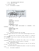


STAND ALONE OPERATION
+12V(B+) ANT
DOOR LOCK INPUT
DOOR UNLOCK INPUT
DOOR DOOR
LOCK UNLOCK B+
DOOR PIN INPUT
TRUNK INPUT MAIN
START KILL
DOOR TX MODULE
OUTPUT
OPEN TRUNK
PIN OPEN
B+
ENGINE
B+ ON
START INPUT
ACC (KEY)
SIREN OUTPU
(ARMED INPUT)
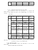
HARNESS A
’
SSY AND COLOR CODE
1. PIN14 : RED - +12V 2. PIN13 : BROWN
–
ACC2
3. PIN12 : GREEN
–
DOOR LOCK 4. PIN11 : BLUE
–
DOOR UNLOCK
5. PIN10 : VIOLET
–
START IN 6. PIN9 : GRAY
–
TRUNK
7. PIN8 : WHITE
–
SHOCK SENSOR 8. PIN7 : YELLOW
–
DOOR INPUT
9. PIN6 : LIGHT BLUE
–
ARMED INPUT 10. PIN5 : PINK
–
HORN OUT
11. PIN4 : YELLOW/BLACK
–
START KILL 12. PIN3 : BLACK - GND
13. PIN2: NONE 14. PIN1 : NONE
2. FCC Information
Caution : Any changes or modifications in construction of this device which are not expressly
approved by the party responsible for compliance could void the user's authority to operate
the equipment.
3. FCC Label Information
This device complies with part 15 of the FCC Rules.
Operation is subject to the following two conditions:
(1)This device may not cause harmful interference, and
(2)this device must accept any interference received,
including interference that may cause undesired operation.