
User`s guide

3-19
CH 3/ View Real Time Data
Sample 3-Phase,
three wire delta
rotation
(continued)
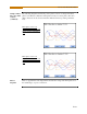
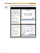
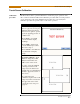
The following diagrams describe the positive phase rotation of voltage and current
phasors (for Resistive, Inductive and Capacitive loads) for a three phase, three wire
delta connection. An arrow head on the line indicates direction pointing toward the
load.
Three phase vectors are
displayed as three lines, 120
degrees apart in an Inductive
load
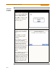
Three phase vectors are
displayed as three lines, 120
degrees apart in a Capacitive
load
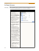
Phasor
diagrams
Refer to Appendix E for the diagrams that describe the voltage and current phasors for
the standard type of power connections.
MARK243
MARK244