360mm BANDSAW ■ STOCK No.36761 ■ PART No.BS355A • INSTRUCTIONS • IMPORTANT: PLEASE READ THESE INSTRUCTIONS CAREFULLY TO ENSURE THE SAFE AND EFFECTIVE USE OF THIS TOOL. 12/2000 GENERAL INFORMATION This manual has been compiled by Draper Tools and is an integrated part of the power tool equipment, which should be kept with the machine. This manual describes the purpose for which this tool has been designed and contains all the necessary information to ensure its correct and safe use.
360mm BANDSAW ■ STOCK No.36761 CONTENTS: ■ PART No.BS355A Page No. Contents/Declaration .......................................................................................1 Specification/Guarantee...................................................................................2 Power Supply ...................................................................................................3 General Safety Instructions ..............................................................................
SPECIFICATION The Draper Tools policy of continuous improvement determines the right to change specification without notice. Part No. ................................................................................................................BS355A Stock No...................................................................................................................36761 Maximum cutting height........................................................................................139mm Throat depth.
POWER SUPPLY CONNECTING YOUR MACHINE TO THE POWER SUPPLY: (230V) To eliminate the possibility of an electric shock your machine has been fitted with a BS approved, non rewireable moulded plug and cable which incorporates a fuse, the value of which is indicated on the pin face of the plug. Should the fuse need to be replaced an approved BS1362 fuse must be used of the same rating, marked thus . The fuse cover is detachable, never use the plug with the cover omitted.
GENERAL SAFETY INSTRUCTIONS FOR POWER TOOLS WARNING Please read the following instructions carefully, failure to do so could lead to serious personal injury. IMPORTANT Draper Tools Limited recommends that this machine should not be modified or used for any application other than that for which it was designed. If you are unsure of its relative applications do not hesitate to contact us in writing and we will advise you. 1. 2. 3. 4. 5. 6. 7. 8. 9. 10. 11. 12. 13. 14.
ADDITIONAL SAFETY RULES FOR BANDSAWS/DISCS AND STRIP SANDERS 14. Permanently fix your bandsaw to a bench before performing cutting operations. (See ‘Fastening to a Workbench’, page 9). 1. Lower the blade guard to within approximately 3mm above the material being cut. 2. Always keep hands and fingers away from the saw blade, especially when coming to the end of a cut. 15. Use in a well ventilated area and dust extraction to minimise airborne dust. 3.
UNPACKING AND CHECKING CONTENTS WARNING For your own safety, do not connect the plug to the power supply until all the assembly steps are completed and you have read and understood the safety and operational instructions. Carefully unpack the bandsaw and all the loose items from the carton. The photograph below, illustrates the bandsaw and all the loose parts. Refer to Fig.1. Check that all the parts are present. If any parts are damaged or are missing, please call the Draper Helpline on (023) 8049 4344.
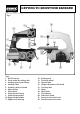
GETTING TO KNOW YOUR BANDSAW Fig.2. Fig.2. 1. No Volt switch 2. Drive wheel & sanding disc 3. Sanding guard (not shown) 4. Sanding table 5. Sanding table lock knob 6. Motor pulley 7. Idler wheel 8. Lower back bearing 9. Lower blade guides 10. Upper blade guides 11. Upper back bearing 12. 13. 14. 15. 16. 17. 18. 19. 20. 21. 22.
ASSEMBLY Your bandsaw is supplied assembled except for the work and sanding table. To assemble the worktable to the bandsaw: 1. Remove the table lock knob $ , spring % and spring support bush & from the table support at the rear of the bandsaw (Fig.3). 2. Remove the hex socket head table alignment screw and clamp from the underside of the worktable.
OPERATION & USE ON/OFF SWITCH When key is in the off/locked position, it will prevent unauthorized operation of the bandsaw (Fig.6). Fig.6. Fig.7. The bandsaw is fitted with a no volt switch. In the event of a power supply failure the bandsaw will have to be manually re-started (Fig.7). CHANGING SPEEDS 1. Turn the main power switch off and disconnect from the power supply. 2. Remove the front cover. 3. Refer to Fig.8. and check which pulley steps to use for the desired speed and adjust as required. 4.
OPERATION & USE CHANGING BLADES 1. Turn the main power switch off and disconnect from the power supply. 2. Remove front cover. 3. Remove the upper blade guard ( , loosen locking screw ) and adjust the upper support bearing * away from the blade (Fig.9). 4. Loosen the upper and lower blade guide locking screws + and move the blade guides away from the blade (Fig.10). 5. Loosen locking screw , and adjust the lower support bearing - away from the blade (Fig.10). 6. Using the hex key supplied .
OPERATION & USE MITRE GUIDE Most cross cut work, especially with small pieces of material are more easily controlled with the aid of the mitre guide 3 . The guide is graduated to 45˚ for assistance in cutting both left and right hand angles. Fig.13. RIP FENCE True straight line rip cutting is best done by guiding the work against the rip fence 2 . The fence can also be used for cutting off exact widths. Fig.14.
OPERATION & USE Remove the saw blade as explained in CHANGING BLADES (page11). Remove the sanding disc guard from the front cover. Mount the support rod 8 of the sanding table through the hole under the sanding disc. Tighten the table lock knob at the left hand side of the bandsaw until the table is held firmly. The sanding table is slotted for use with the mitre guide supplied with your bandsaw. The sanding table can be tilted to 45° for bevel and compound mitre sanding.
TIPS ON USING YOUR BANDSAW WORKTABLE The worktable is a 400x400mm aluminium die-casting. It supports the material being cut and is grooved to accept a mitre guide and rip fence. The rip fence can be attached to both the front and rear of the table. The table can be tilted to every angle from 0-45° making possible a large variety of bevel and compound angle cuts. The tilt indicator beneath the table shows the angle setting.
TIPS ON USING YOUR BANDSAW the table it will help support the work against slip. The width of cut indicator shows the distance between the blade and the rip fence at the table surface. For all cutting operations the upper blade guard should be adjusted to just clear the work being cut (approx. 3mm or 1⁄8"). Not only does this provide the best operator safety, but it also brings the blade guides closer to the work giving more accurate results and easier control.
MAINTENANCE CHANGING TYRES Eventually the rubber tyres on the bandsaw wheels will wear due to the constant contact of the sharp teeth of the blade. Remove the blade, lift the edge of the tyre with a small screwdriver and the tyre can be worked off the wheel easily.We recommend that the three tyres be changed at the same time. (See Spare Parts Listing/Drawing). Refit blade BLADE GUIDES Blade guides should be inspected regularly for wear or chipping.
NOTES - 16 -
NOTES - 17 -
NOTES - 18 -
DRAPER TOOLS LIMITED, Hursley Road, Chandler's Ford, Eastleigh, Hants. SO53 1YF. U.K. Helpline: (023) 8049 4344. Sales Desk: (023) 8049 4333. General Enquiries: (023) 8026 6355. Fax: (023) 8026 0784. http://www.draper.co.uk e-mail: sales@draper.co.uk YOUR DRAPER STOCKIST ©Published by Draper Tools Ltd.