
Operating instructions
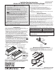

Accessory Access ACXLE & ACXLV Roller Installation
Please note: When ordering a motor with built-in Low Voltage Controller, if
the case ships separate from the "guts," the case includes the 25' cable and
special low voltage switch.
1 Remove the bottom access panel (see "Bottom Access Panel Installation/
Removal" section above).
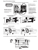
2 The motor end mounting bracket has a metal bracket with snap ring for
accepting motor head. The idler end mounting bracket has spherical ball
bearings for accepting the idler pin. Both brackets have four set screws that
will be used to tighten the brackets in place inside the case. Back out the
four set screws in bracket until they are flush with top side of bracket, then
remove the roller assembly from the shipping brackets, placing the roller
assembly on a flat, clean surface (see Fig. 5).
Please Note: Do not lose the snap ring and screw from the motorized
end, or the eight nylon washers, spring lock washer, fender washer and
machine screw from the idler end. They are required for re-attaching the
roller assembly to the brackets inside the case.
3 To engage the motor end bracket flange above the two channels in the top
of the screen housing, rotate the bracket approximately 45° counter-
clockwise to allow the top surface of the motor bracket to rest flat against
the top inside of the housing. Rotating the bracket clockwise until it is
engaged with the mounting channel, slide it along the length of the housing
against the electrical junction box. Note: Set screw collar side of the bracket
must point toward the center of the case.
Caution: Do not allow the bracket to rotate and fall out of the channel.
4 Tighten all four set screws.
Motorized Roller/Fabric Removal
Reverse the instructions above “Motorized Roller/Fabric Installation” for
removal of the unit.
Operation
When screen is first operated, be cautious! Cycle unit down and up several
times to confirm satisfactory operation.
110-120V SINGLE STATION CONTROL—3-position UP-OFF-DOWN switch
permits operation to be stopped at any point. Factory adjusted limit switches
automatically stop screen when fully down or fully up.
110-120V MULTIPLE STATION CONTROL—Switches are similar in
appearance to 110-120V Single Station Control. Screen stops when switch
is released and may be restarted in either direction. Factory adjusted limit
switches stop screen automatically when fully down or fully up.
24V CONTROL—Three-button UP-STOP-DOWN switches stop at any
point desired, operate in any sequence. Factory adjusted limit switches
automatically stop screen when fully down or fully up. Installer should
incorporate an all-pole disconnect in the fixed wiring.
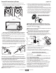
Access XL case as seen from below
Bottom flange of Access XL housing
Bottom access panel pushup
points for panel removal
Caution: Beware of pinch
points at ends of closure
Figure 4
2 Disengage closure from extrusion inside the case. Rotate closure as
shown in Fig. 4 and remove, holding it so the closure remains in this posi-
tion and does not bow before placing it on a flat surface.
Access XL Instructions by Draper page 2 of 5
www
.draperinc.com
(765) 987-799
9
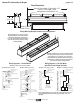
5 Replace the eight Nylon Washers into the idler end of the roller assembly.
6 Loosen the carriage bolts which attach the flange-mounted bearing to the
idler end bracket just enough to allow the bushing some limited movement,
which will help when installing the roller assembly.
7 Rotate the bracket into the mounting channel located in the case top (when
mounting the roller assembly into the case). Both the bracket flange and set
screw collar side of the bearing must point toward the gudgeon assembly.
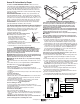
8 Raise the roller/fabric assembly up into the screen housing and engage the
head of the motor completely into the motor mounting bracket, making sure
the snap ring engages with the motor and that the limit switch adjusting
knobs are visible from the bottom of the screen housing (see Fig. 6).
Caution: Due to the weight of the roller assembly, this step requires at
least two people to perform safely.
9 While supporting the idler end of the roller, slide the idler end mounting
bracket toward the roller. Slide the bearing over the end of the shaft.
Caution: Do not allow bracket to rotate and fall out of channel!
Align the bracket into the housing and tighten all four of the set screws.
Lock the roller assembly into place on the mounting bracket with the fender
washer, spring lock washer and machine screw (see Fig. 7).
Re-tighten the carriage bolts in the Idler-end Bracket Assembly so that the
flange-mounted bearing is locked in place (see Fig. 5).
Tighten the two set screws in the bearing collar.
Connect electrical plug from motor to mating socket on junction box.
Reinstall the bottom access panel as previously described (see Figs 3 & 4).
Caution: When placing the roller assembly into the case, be sure
motor is fully re-seated in the bracket, and secure it carefully with the
motor retaining spring and screw. Limit adjustment screws should be
facing down to allow access to them.
Please note: Maximum torque for
tightening screw is 5 lb-inches.
Figure 6
OR
Figure 7
8 Nylon
Washers
Idler End
Roller Bracket
Fender
Washer
Spring
Lock
Washer
Machine
Screw
Roller
Setscrews
Gudgeon
Assembly
Carriage
Bolts
Bearing
Collar
Setscrews
Motor End (Series V shown) Idler End (Series E shown)
Figure 5
Carriage
Bolt
Shipping Brackets