
Operating instructions

Access XL Instructions by Draper page 3 of 5
Limit Adjustments (Standard Motor)
Please Note: Screen limits are factory set for optimum performance of
the screen. A procedure is outlined below for minor tweaks, but any
adjustment of these limits may negatively affect the flatness of the
screen surface and could also void the warranty. Please check with
Draper prior to resetting screen limits.
CAUTION: Always be prepared to shut screen off manually when new
adjustment is being tested. Screen may be severely damaged if viewing
surface is allowed to run too far up or too far down.
CAUTION: Be sure all switches are in “off” position before adjusting
limit switches.
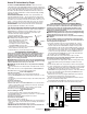
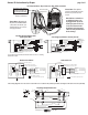
The motor limit screws are normally located on the audience left of screen
roller.
**Please Note: If the Access XL is “Right Hand Motor”, WHITE/DOWN and
YELLOW/UP limit screws are reversed. See graphic below.
"Down" Limit Adjustment
To Reduce Screen Drop
1 Raise screen surface about 1' above desired setting and turn off.
2 Turn the WHITE/DOWN limit screw clockwise (three screw turns = ½ roller
revolution).
3 Test by running screen down and repeat steps 1 and 2 until desired position
is reached.
To Increase Screen Drop
1 Run screen to the down limit.
2 With the down switch on, turn WHITE/DOWN limit screw counterclockwise
(3 turns of screw equals ½ roller revolution) to increase drop. Screen will
drop automatically for each turn.
3 Test by running screen up about 1' and back down to new down limit.
4 Repeat steps 2 and 3 until desired position is reached.
"Up" Limit Adjustment
Screen is Running Too Far Up
1 Lower screen surface about 1' below desired setting and turn off.
2 Turn YELLOW/UP limit screw clockwise (3 screw turns = ½ roller revolution).
3 Test by running screen up.
4 Repeat steps 1 through 3 until desired position is reached.
Screen Needs to Run Up More
1 Run screen down about 1' and turn off.
2 With the up switch on, turn the YELLOW/UP limit screw counterclockwise (3
turns of screw equals ½ roller revolution). Screen will drop automatically for
each turn.
3 Repeat steps 1 and 2 until desired position is reached.
CAUTION: Do NOT allow the dowel to wrap up over the roller when the
screen is running up! This could damage the screen.
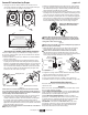
Tab-Tension Adjustment Procedure for Access XL/Series V
Draper’s Tab-Tensioning System is factory-set; under normal circumstances
field adjustment is not required. If you notice wrinkles, waves or other
indications that tensioning cables need adjusting, follow these steps:
1 Determine which side requires adjustment.
2 Secure dowel with one hand.
Caution: Don't touch or bend viewing surface.
3 Use Phillips-head screwdriver to push in
spring-loaded adjustment screw. Slowly
turn clockwise to tighten tension or
counterclockwise to loosen tension. The
screw adjusts in ¼ turn increments. Adjust
only one increment (¼ turn) at a time.
4 If problem is not corrected, leave screen in position for 24 hours to allow
surface material to stretch into position.
5 If problem still is not corrected, repeat steps 2 and 3.
Dowel
Adjustment
Screw
Te nsioning
Cable
www
.draperinc.com
(765) 987-799
9
110-120V & 12V VIDEO INTERFACE CONTROL—Allows screen to be
controlled by trigger signal (100 milliAmp minimum)—when the signal comes
on, the screen descends automatically. Two versions: Model VIC115 integrates
screen operation with a Draper video projector lift or a video projector or
tuner with a 110-120V switched outlet. Model VIC12 interfaces with a 12V
switched outlet. Both available with an override switch (VIC–OS), permitting
independent operation.
KEY OPERATED SWITCHING—Two kinds of key-operated switches are
optionally available with this unit. The key-operated power supply switch
controls power to the screen and switches. When it is “off”, the switches will
not operate screen. Key may be removed from the switch in either “on” or “off”
position. A three-position key switch permits the screen to be operated
directly by key. In this case, the screen’s operator must always have a key.
RS232/ETHERNET—Serial communication and network communication
optionally available with wall switches, RF or IR remote.
Limit Adjustments (Built-in Low Voltage Motors)
Please Note: Screen limits are factory set for optimum performance of
the screen. A procedure is outlined below for minor tweaks, but any
adjustment of these limits may negatively affect the flatness of the
screen surface and could also void the warranty. Please check with
Draper prior to resetting screen limits.
CAUTION: Always be prepared to shut screen off manually when new
adjustment is being tested. Screen may be severely damaged if viewing
surface is allowed to run too far up or too far down.
CAUTION: Be sure all switches are in “off” position before adjusting
limit switches.
Please note: When ordering a motor with built-in Low Voltage Control-
ler, if the case ships separate from the "guts," the case includes the 25'
cable and special low voltage switch.
1 Connect the ILT switch to the motor via the terminal blocks, or via the
modular port using four conductor modular cable. When using modular
cable, the cable connectors MUST NOT be crimped in reverse, as with
standard telephone cable. (For Dry Contacts Wiring Diagram, see page 4.)
2 Set the slide switch to the lower position. Press and hold the DOWN button
on the switch to move the viewing surface to the desired lower limit. If the
screen moves in the opposite direction, release the DOWN button and
press and hold down the STOP button for four seconds. This will reverse
the operation of the UP and DOWN switches.
3 Move slider switch into center position. Wait a couple of seconds.
Please Note: If you move the slider switch from down to up in one mo-
tion it sets the two limits in the same position.
4 Set the slide switch to the higher position. Move the viewing surface to the
desired upper limit by pressing and holding the UP button on the wall
switch.
5 Return the slide switch to the center position to return to normal operation.
6 To set the viewing surface to an alternate format position, move the viewing
surface to the desired position and press the STOP button. Press and hold
the STOP button for at least three seconds to record the position.
Please Note: Pressing and releasing the UP button on the switch will move
the screen to its upper limit. Pressing and releasing the DOWN button will
move the screen to its lower limit.
While the motor is in motion, pressing the STOP button for less than two
seconds will stop the viewing surface at its present position.
Once the motor is stopped, pressing the STOP button will move the view-
ing surface to its alternate format position.
Pressing and holding the STOP button, when the motor is at rest or in mo-
tion, for at least three seconds will record a new alternate format position.
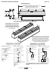
POSITION
FUNCTION
DOWN
UP
CENTER
Set LOWER limit
Set UPPERlimit
Normal Operation
STO P
To Motor
with
Built-In
Low Voltage
Slide
Switch
Back View
U
p
D
o
w
n
C
o
m
m
o
n
+
5V
DC
To Motor
with
Built-In
Low Voltage
POSITION
FUNCTION
DOWN
UP
CENTER
Set LOWER limit
Set UPPERlimit
Normal Operation
STO P
To Motor
with
Built-In
Low Voltage
Slide
Switch
Back View
U
p
D
o
w
n
C
o
m
m
o
n
+
5V
DC
To Motor
with
Built-In
Low Voltage
Left Hand
Motor Location
Right Hand
Motor Location
(Fabric from
back of roller)
(Fabric over
front of roller)
Audience
Side
Audience
Side
Please Note: 5V DC must be
connected to be able to set
limits using the wall switch.