
Operating instructions

Access XL Instructions by Draper page 4 of 5
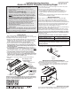
Case Dimensions
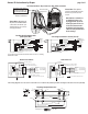
*These wiring diagrams are for Access XL screens with motor on audi-
ence left (standard), and fabric unrolling from the back of the roller
(standard).
www
.draperinc.com
(765) 987-799
9
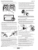
Single Station Control
Internal Screen Wiring
White (Common)
Black (Down)
Red (Up)
Green/Yellow (Ground)
Dashed wiring
by electrician
Control
switch
Single gang box by others
Min. 4" x 2
1
/
8
" x 1
7
/
8
" deep
Blue
Black
Red
Location of key
operated on-off
switch if furnished
To 110-120V Line
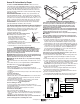
Multiple Station Control
Internal Screen Wiring
White (Common)
Black (Down)
Red (Up)
Green/Yellow (Ground)
Dashed wiring
by electrician
Red
Red
Black
Blue
Blue
Cap off with wire
nut and tape
Black
Red
Blue
Black
Single gang box by others
Min. 4" x 2
1
/
8
" x 1
7
/
8
" deep.
3 shown. More or less equally
feasible.
Location of key
operated on-off
switch if furnished
To 110-120V Line
Wiring Diagrams—110-120V Motor
Wiring Diagrams—110-120V Motor
with Built-in Low Voltage Controller
Single Low Voltage Control
Internal Screen Wiring
White (Neutral)
Black
Green/Yellow (Ground)
Dashed wiring
by electrician
To 110-120V Line
Multiple Low Voltage Controls
Internal Screen Wiring
White (Neutral)
Black
Green/Yellow (Ground)
Dashed wiring
by electrician
To 110-120V Line
Wall Switch,
RF or IR
Receiver,
or integrated
control system
Wall Switches,
RF or IR
Receivers,
or integrated
control systems
Data Cable
Data
Cables
RJ-9
connector
RJ-9
connectors
Please Note: Do not wire motors in parallel.
L
Series V-L=varies
Series E-L=6
3
/8"
9"
7¾"
8½"
9½"
10"
Evenly Spaced
Evenly Spaced
Evenly Spaced
Centered over roller bracket (+/- 4")
1"
10
7
/16"
Series E Case Length = Fabric width + 12
3
/4"
Series V Case Length = Varies
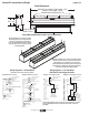
Ceiling Mounting Bracket Locations and Configurations
Typical Installation: Two outermost ceiling
mounting brackets (on the ends) must be
centered over the interior roller brackets
(+/- 4"). Two intermediate brackets should be
spaced evenly from the outermost ceiling
mounting brackets.
Alternate Installation: Two outermost ceiling mounting
brackets (on the ends) are centered over the interior
roller brackets (+/- 4"), parallel to the case. The two
intermediate brackets should be placed in the typical
perpendicular configuration, and spaced evenly from
the outermost ceiling mounting brackets.