
Operating instructions
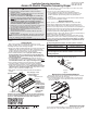

Access XL Instructions by Draper page 5 of 5
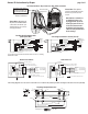
*These wiring diagrams are for Access XL screens with motor on audience left (standard), and fabric unrolling from the back of the roller (standard).
www
.draperinc.com
(765) 987-799
9
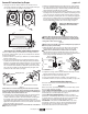
Two-Way Serial Communication
(RS232) with MC1
See separate Serial Communication-RS232 Instruction sheet for enabling
RS232 with the MC1.
RS232 Data FROM Control System
RS232 Data TO Control System
Signal Ground & Manual Switch Common
Manual Switch Down
Manual Switch Up
White-Common to screen & 110-120V AC Neutral
Red-to Screen (directional)
Brown-to Screen (directional)
Black-Hot to 110-120V AC
Green/Yellow-Ground
Fuse
Program LED
Eye Port for IR Eye. For RF Receiver or LED
Wall Switch, a Splitter and a Power Supply
is required. Plug RF Receiver or LED Wall
Switch and Power Supply into splitter, then
run cable from Splitter to MC1 Eye Port.
Low Voltage Wiring by others
AC Wiring by electrician
MC1
White (Common)
Red (Up)
Black (Down)
Green/Yellow (Gnd)
Internal Screen Wiring
Location of key
operated on-off
switch if furnished
To
110-120V
Line
STOP
Control
Switches
24v DC
STOP
3
/8"
1
3
/8"
1
/8"
1
/2"
R
1
/4"
1
/4"
R
1
/8"
5
/16"
4
1
/2"
3
/16"
5
/16"
3
/16"
1
1
/8
"
1
/4"
1
1
/4"
4
13
/16"
9"
7
3
/4"
1
1
/2"
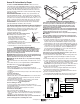
Mounting Bracket Dimensions
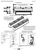
the +5V
UP
5V
COM
DWN
U
P
D
O
W
N
C
O
M
M
O
N
5V
Motor Data Cable
plugged in here
ILT Switch-to-Motor—Dry Contacts or Data Cable connection
Please Note: This Splitter/
Jack is located inside the junc-
tion box of your Access XL
screen.
Back of wall switch.
Please Note: Although both
Dry Contact and Data Cable
connections are shown, you
should only use one connec-
tion type per motor.
Data Cables to switches or
to additional motors can
be plugged into any of the
three open jacks. If this is a
"Case First, Screen Later"
installation, plug the motor
cable into the jack indicated
in the drawing.
3 Button Wall Switch
DOWN - Black
COM - White
UP - Red
White or Blue-Common to screen & 110/220V AC Neutral
Red-to screen (directional)
Brown-to screen (directional)
Ye llow-to 110/220V AC-Hot
Black-to 110/220V AC-Hot
Green/Yellow (Ground)
Eye Port for IR Eye, RF Receiver or LED
Wall Switch. For more than one of
these, a splitter is required.
Aux Port for connecting additional LVC-III
modules (up to six total can be linked-
connect from Aux to Eye).
Dashed wiring by electrician
Low voltage wiring by others
White/Blue (Common)
Red 110/Black 220 (Up)
Black 110/Brown 220 (Down)
Location of key
operated on-off
switch if furnished
To
110/220V
Line
Internal
S
creen Wiring
STOP
Control
Switches
24v DC
STOP
Green/Yellow
(Motor Ground)
Low Voltage and Wireless Control (LVC-III)
Built-In VIC-12/VIC-6* Built-In VIC-115*
Green/Yellow
Black
White
Green
Green
Red
Black
White
Ground
#2 Up
#1 Down
Common
Jacketed Motor Cable
110-120 VAC
Screen Motor
Ring Te rminal on each Ground Wire
with Star Washer screwed to Spine
HSG. Cap
HSG. Plug
2
5
1
115 Volt Relay
Wire connected with Quick Disconnect
:
:
::
Black
Red
:
:
:
:
:
:
:
:
:
:
:
:
:
:
:
:
:
:
:
:
4
6
87
3
Black Lead
White Lead
Green/Yellow
Black
White
Green
Green
Red
Black
White
Ground
#2 Up
#1 Down
Common
Jacketed Motor Cable
110-120 VAC
Screen Motor
Ring Te rminal on ground wire
riveted to J-Box with Star Washer
HSG. Cap
HSG. Plug
:
:
::
:
:
::
:
:
::
Brown (-)
Orange (+)
14
13
9
5
1
12 Volt (VIC-12) or 6 Volt (VIC-6) Relay
Wire soldered to terminal
Wire connected with Quick Disconnect
:
:
::
Red
Black
Please Note: 5V DC must be
connected to be able to set
limits using the wall switch.