BELT AND DISC SANDER ■ STOCK No.50021 ■ PART No.BDS368 • INSTRUCTIONS • IMPORTANT: PLEASE READ THESE INSTRUCTIONS CAREFULLY TO ENSURE THE SAFE AND EFFECTIVE USE OF THIS TOOL. 02/2001 GENERAL INFORMATION This manual has been compiled by Draper Tools and is an integrated part of the power tool equipment, which should be kept with the machine. This manual describes the purpose for which this tool has been designed and contains all the necessary information to ensure its correct and safe use.
BELT AND DISC SANDER ■ STOCK No.50021 CONTENTS: ■ PART No.BDS368 Page No. Contents/Declaration ..................................................................................... 1 Specification/Guarantee ................................................................................. 2 Power Supply .................................................................................................. 3 Safety Warning/General Safety Instructions ...................................................
SPECIFICATION The Draper Tools policy of continuous improvement determines the right to change specification without notice. Part No. ................................................................................................................ BDS368 Stock No. ................................................................................................................ 50021 Belt size ......................................................................................................
POWER SUPPLY CONNECTING YOUR MACHINE TO THE POWER SUPPLY: (230V ONLY) To eliminate the possibility of an electric shock your machine has been fitted with a BS approved, non rewireable moulded plug and cable which incorporates a fuse, the value of which is indicated on the pin face of the plug. Should the fuse need to be replaced an approved BS1362 fuse must be used of the same rating, marked thus . The fuse cover is detachable, never use the plug with the cover omitted.
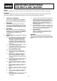
GENERAL SAFETY INSTRUCTIONS FOR POWER TOOLS WARNING Please read the following instructions carefully, failure to do so could lead to serious personal injury. IMPORTANT Draper Tools Limited recommends that this machine should not be modified or used for any application other than that for which it was designed. If you are unsure of its relative applications do not hesitate to contact us in writing and we will advise you. 1. 2. 3. 4. 5. 6. 7. 8. 9. 10. 11. 12. 13. 14.
ADDITIONAL SAFETY RULES FOR BELT & DISC SANDERS SAFETY Safety is a combination of operator common sense and alertness at all times when the sander is being used. WARNING For your own safety, do not attempt to operate the belt and disc sander until it is completely assembled and installed according to the instructions and until you have read and understand the following. 1.
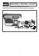
UNPACKING & CHECKING CONTENTS Carefully unpack the sander and all the loose parts from the carton. Fig.1 illustrates the sander and all the associated parts. Check that all of the parts are present. If some parts are missing, contact the Draper Helpline on (023) 8049 4344. Fig.
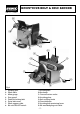
KNOW YOUR BELT & DISC SANDER ✕✙✌ ✕✗✌ ✙✌ ✕✕✌ ✛✌ ✚✌ ✕✔✌ ✕✘✌ ✗✌ ✕✖✌ ✛✌ ✢✌ ✕✌ ✜✌ ✗✌ ✕✖✌ ✖✌ ✕✙✌ ✘✌ ✜✌ Fig.2 1. 2. 3. 4. 5. 6. 7. 8. Sanding disc Work table Mitre gauge Disc guard Table tilt locking bolt Drive belt cover Work support table No-volt ON/OFF switch 9. Sanding belt 10. Backstop 11. Dust extraction outlet 12. Sanding plate 13. Belt tracking knob 14. Dust deflector 15. Sanding belt tensioning lever 16.
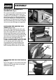
ASSEMBLY MOUNTING THE SANDER TO A WORKBENCH (Fig.3): The sander should be fastened securely to a firm supporting surface such as a workbench. If mounting to a workbench, place the sander in a suitable position and mark the surface through the holes in the base ✪✌. Remove the sander and drill the holes, align and insert the bolts and nut securely (fixings not supplied). INSTALLING THE SANDING DISC TABLE (Figs.4 & 5): Locate the table ✫✌, bracket ✬✌ and securing handle ✭✌.
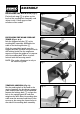
ASSEMBLY INSTALLING THE BACK STOP (Fig.7): Fix the back stop ✰✌ in place on the back of the sanding belt assembly and adjust it with 1.5mm gap to allow sawdust to flow under. INSTALLING THE WORK SUPPORT TABLE (Figs.8 & 9): Bolt the support bracket ✱✌ to the sanding belt assembly. Assemble the table to the locking bracket ✲✌. Slide the assembled guide onto the support bracket and lock into place with the locking knob. Use the engineers square to adjust the guide so it is square with the sanding belt.
ASSEMBLY SAW DUST EXTRACTION (Fig.11): It is recommended that the sander is connected to a vacuum cleaner (for example Draper Stock No.64674) during operation, which will provide fast and efficient removal of saw dust. Fig.11 NOTE: Due to the large size outlet for the dust extraction, Stock No.29786 hose and 29791 adaptor are recommended. OPERATION AND USE NO-VOLT ON/OFF SWITCH (Fig.12): Note: The BDS368 is fitted with a no-volt on/off switch.
OPERATION AND USE STRAIGHT SANDING (Fig.13): Hold the work firmly with both hands, keeping fingers away from the belt. Straight pieces shorter than the belt table are sanded by holding the workpiece lightly against the belt. Move it back and forth across the belt, keeping the end butted against the stop fence. This fence prevents the workpieces from slipping off the table. USE EXTRA CAUTION WHEN SANDING THIN PIECES. When finishing long pieces, remove the stop fence.
CONTOUR SANDING (Fig.15): Inside contours: Inside curves can be sanded on the drums at either end of the machine. Hold the work firmly, press the contour lightly against the drum on one side and move the work slowly across the drum while moving up the contour against the drum. Outside contours: Outside curves can be sanded on the belt table of the unsupported side of the belt with the table in the vertical position. Hold the work firmly.
OPERATION AND USE REPLACING THE SANDING BELT AND TRACKING (Fig.17): WARNING - TO AVOID INJURY FROM ACCIDENTAL STARTING, TURN THE POWER SWITCH “OFF” AND REMOVE THE PLUG FROM THE POWER SUPPLY BEFORE REMOVING OR INSTALLING SANDING BELTS. On the inside of the sanding belt you will find “direction arrows”. The sanding belt must run in the direction of these arrows so that the splice does not come apart. 1. Loosen the bed locking screw ✴✌ and lift the bed to approx. 45º, Fig.17. 2.
MAINTENANCE WARNING: FOR YOUR OWN SAFETY, TURN SWITCH “OFF” AND REMOVE THE PLUG FROM THE POWER SUPPLY OUTLET BEFORE ADJUSTING, MAINTAINING, OR LUBRICATING YOUR BELT AND DISC SANDER. Do not apply wax to the abrasive belt table because the belt could pick up the wax and d deposit it on the pulleys, causing the belt to slip. If power cable is worn, cut, or damaged in any way, have it replaced immediately. Keep machine clean and remove accumulations of dust.
OPTIONAL ACCESSORIES The following accessories are available from your local Draper stockist: SANDING DISCS: PART No. STOCK No. GRIT GRADE PACK QUANTITY SD8 51005 60 5 discs SD8 51006 80 5 discs SD8 51007 100 5 discs SD8 51008 120 5 discs SD8 51009 Assorted 5 discs PART No. STOCK No.
NOTES - 16 -
NOTES - 17 -
NOTES - 18 -
DRAPER TOOLS LIMITED, Hursley Road, Chandler's Ford, Eastleigh, Hants. SO53 1YF. U.K. Helpline: (023) 8049 4344. Sales Desk: (023) 8049 4333. General Enquiries: (023) 8026 6355. Fax: (023) 8026 0784. www.draper.co.uk e-mail: sales@draper.co.uk YOUR DRAPER STOCKIST ©Published by Draper Tools Ltd.