DRILL PRESS ■ STOCK No.36389 52062 ■ PART No.D16/16 D16/16F • INSTRUCTIONS • IMPORTANT: PLEASE READ THESE INSTRUCTIONS CAREFULLY TO ENSURE THE SAFE AND EFFECTIVE USE OF THIS TOOL. 02/2001 GENERAL INFORMATION This manual has been compiled by Draper Tools and is an integrated part of the power tool equipment, which should be kept with the machine. This manual describes the purpose for which this tool has been designed and contains all the necessary information to ensure its correct and safe use.
DRILL PRESS ■ STOCK No.36389 52062 ■ PART No. D16/16 D16/16F CONTENTS: Page No. Declaration of Conformity..............................................................................................1 Specification/Guarantee ................................................................................................2 Power Supply .................................................................................................................3 General Safety Instructions ..............................
SPECIFICATION The Draper Tools policy of continuous improvement determines the right to change specification without notice.
POWER SUPPLY CONNECTING YOUR MACHINE TO THE POWER SUPPLY: (230V) To eliminate the possibility of an electric shock your machine has been fitted with a BS approved, non rewireable moulded plug and cable which incorporates a fuse, the value of which is indicated on the pin face of the plug. Should the fuse need to be replaced an approved BS1362 fuse must be used of the same rating, marked thus . The fuse cover is detachable, never use the plug with the cover omitted.
GENERAL SAFETY INSTRUCTIONS FOR POWER TOOLS WARNING Please read the following instructions carefully, failure to do so could lead to serious personal injury. IMPORTANT Draper Tools Limited recommends that this machine should not be modified or used for any application other than that for which it was designed. If you are unsure of its relative applications do not hesitate to contact us in writing and we will advise you. 1. 2. 3. 4. 5. 6. 7. 8. 9. 10. 11. 12. 13. 14.
ADDITIONAL SAFETY RULES FOR DRILL PRESSES 1. This drill press is intended for use only with drill bits. The use of any other accessories may be hazardous. 2. CHECK to see that the drill bit is securely locked in the chuck. 3. CORRECT DRILLING SPEEDS Important factors which determine the best speed to use in any drill press operation are: (a) The smaller the drill the greater the required r.p.m. (revolutions per minute) (b) In soft materials the speed should be higher than for hard materials. 4.
GETTING TO KNOW YOUR DRILL PRESS MOTOR PULLEY COVER MOTOR PULLEY INTERMEDIATE PULLEY SPINDLE PULLEY SPECIFICATION LABEL DOWN FEED ASSEMBLY CHUCK GUARD CHUCK TABLE TABLE LOCKING HANDLE COLUMN BASE RACK TABLE RISE AND FALL HANDLE RACK SECURING RING NO-VOLT TYPE ON/OFF SWITCH DRIVE BELT - TENSION ADJUSTER RISE AND FALL LOCKING HANDLE -6-
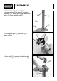
ASSEMBLY ASSEMBLING THE DRILL PRESS 1. Secure column $ to base % using the four bolts & . Loosen grub screw and remove collar ' along with the rack ( . Fig.2. ' ( $ & % 2. Locate worm gear ) into hole * as shown in Fig.3. Fig.3. 3. Place rack + in position in table bracket, as shown in Fig.4. and slide onto column , . Fig.4.
ASSEMBLY 4. Ease table bracket and rack all the way down onto the column. Replace collar - and retighten the grub screw, locking rack . into place. Fig.5. - . 5. Slide table / into the table bracket as shown in Fig.6 and lock into place using the table locking handle 0 . Fig.6. / 2 6. Fix table raising handle 1 and bracket locking handle 2 as shown in Fig 6. 0 7.Place the drill press head 3 onto column as far as it will go (seek assistance as it is heavy).
ASSEMBLY 8. Screw the three downfeed handles 5 into the three holes located in the pinion shaft as shown in Fig 8. 5 Fig.8. 9. Making sure that the chuck 6 is opened to its capacity, place it down on a bench. Clean any excess grease off the large end of the spindle 7 . Insert the taper into the back of the chuck and with a scrap piece of timber and a hammer firmly tap them together. 7 6 Fig.9. 10. Loosen the nut and bolt 8 Fig.10 and slide the chuck guard 9 up onto the collar : .
OPERATION AND USE NO-VOLT ON/OFF SWITCH: (Fig 12) The drill is fitted with a no-volt switch = . Fig.12. In the event of a power failure the drill press will have to be manually re-started. To switch the drill press on push the button marked , . To switch the drill press off push the button marked 2 . To switch the drill press off in an emergency strike the 2 button.
OPERATION AND USE SPINDLE SPEEDS Sixteen spindle speeds of: 240, 320, 360, 470, 540, 580, 860, 880, 1130, 1270, 1350, 1560, 1990, 2020, 2480 and 3150 are available with your drill. The highest speed is obtained when the belt is on the largest step of the motor pulley and the smallest step of the spindle pulley as shown in Fig. 13. Fig.13. CHANGING SPEEDS AND ADJUSTING BELT TENSION 1. Disconnect the drill press from the power supply. 2. Remove the pulley cover locking screw $ Fig.
OPERATION AND USE 1. The table * Fig. 17 can be raised or lowered on the drill press column by loosening the table clamp handle + and turning the table raising and lowering handle , . After the table is at the desired height, tighten handle + . Fig.17. * + , 2. The table can be rotated 360º on the table bracket by loosening lock handle - Fig. 18. 3. The table can be tilted right or left by unscrewing and removing the table alignment stud . Fig. 18. . Fig.18. - Fig.19. / 4.
OPERATION AND USE ADJUSTING SPINDLE RETURN SPRING For the purpose of automatically returning the spindle upward after a hole has been drilled, a spindle return spring is provided in the spring housing 4 Fig. 22. This spring has been properly adjusted at the factory and should not be disturbed unless absolutely necessary. To adjust the return spring, proceed as follows: 1. Disconnect the drill press from the power supply. 2. Loosen the nut 6 approximately 1/4". Do not remove nut 6 from shaft 5 Fig.22. 3.
OPERATION AND USE The following directions will give the inexperienced operator a start on common drill press operations. Use scrap material for practice to get the feel of the machine before attempting regular work. CORRECT DRILLING SPEEDS Factors which determine the best speed to use in any drill press operations are: Type of material being worked, Size of hole, Type of drill or other cutter, Quality of cut desired. The smaller the drill, the greater the required r.p.m.
OPTIONAL ACCESSORIES The following accessories are available from your local Draper stockist. WOOD MORTICING ATTACHMENT 25560 60mm 33686 55mm 36577 55mm DRILL PRESS VICES PART No.DPV Manufactured from cast iron with fully hardened jaws. Carton packed. STOCK No.
NOTES - 16 -
NOTES - 17 -
NOTES - 18-
DRAPER TOOLS LIMITED, Hursley Road, Chandler's Ford, Eastleigh, Hants. SO53 1YF. U.K. Helpline: (023) 8049 4344. Sales Desk: (023) 8049 4333. General Enquiries: (023) 8026 6355. Fax: (023) 8026 0784. www.draper.co.uk e-mail: sales@draper.co.uk YOUR DRAPER STOCKIST ©Published by Draper Tools Ltd.