
Owner`s manual


- 12 -
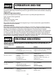
OPERATION AND USE
Fig.17.
Fig.20.
Fig.18.
*
,
+
-
Fig.19.
/
.
1
0
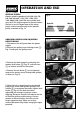
1. The table * Fig. 17 can be raised or
lowered on the drill press column by
loosening the table clamp handle + and
turning the table raising and lowering handle
,. After the table is at the desired height,
tighten handle +.
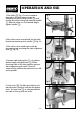
2. The table can be rotated 360º on the table
bracket by loosening lock handle -Fig. 18.
3. The table can be tilted right or left by
unscrewing and removing the table alignment
stud . Fig. 18.
4. Loosen table locking bolt /, tilt table to
desired angle. Retighten bolt /. When
returning table to the level position replace
table alignment grub screw. This will
automatically position the table surface at 90º
to the spindle.
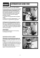
5. A tilt scale 0 Fig. 20 is provided on the
table bracket casting to indicate the degree
of tilt. A cursor line 1 is also provided on
the table to line up with the scale.