
manual


FocalPoint™ Projection Screen by Draper—Assembly Map
144" x 192" (366 x 488 cm) Image Area—4:3 Format
Copyright © 2010 Draper Inc. Form FocalPoint_144x192 _Assy Printed in U.S.A.
®
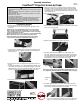
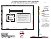
Before you start:
• Spread the tarp (included).
• Assemble the frame and legs before attaching the screen
surface.
• Frame sections should be arranged so that:
➽ Viewing surface attachment posts are on the outside
of the frame
➽ Guide pins should point counterclockwise
➽ Bolt heads should face upward
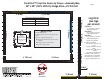
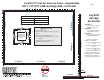
All Pins
should point
counterclockwise.
Bolt heads should
face up.
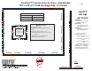
Leg Kit C
(two legs
per screen)
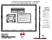
2' (61cm)
4' (122 cm)
3' (91 cm)
3' (91 cm)
4' (122 cm)
4' (122 cm)
3' (91 cm)
Front
3' (91 cm)
4' (122 cm)
4' (122 cm)4' (122 cm)
4' (122 cm)
4' (122 cm)
4' (122 cm)
4' (122 cm)
3' (91 cm)
3' (91 cm)
4' (122 cm)
4' (122 cm)
4' (122 cm)
3' (91 cm)
Caution:
Beware of
pinch points.
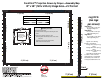
Leg Kit A—
For use with screens up to
80" high viewing area
Leg Kit B—
For use with screens up to
126" high viewing area
Leg Kit C—
For use with screens above
126" high viewing area
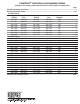
For use with these part numbers
Black-Backed M1300 CineFlex
Silver Anodized Black Silver Anodized Black
385035 385091 385043 385099
Leg Kits come with Leg
Cranks as noted below:
Package A–3 cranks per leg/
total 6
Package B–4 cranks per leg/
total 8
Package C–5 cranks per leg/
total 10
Leg Cranks should be placed
as follows: 1 at the lowest at-
tachment point, 1 at the highest
attachment point, and the rest
evenly spaced between the two.
Page 8