Lotus Service Notes Section EMN ENGINE MANAGEMENT & FUEL INJECTION SECTION EMN - M111 ELISE Section Page Introduction & Component Location EMN.1 3 'Lotus Check' Scanner Tool EMN.2 4 Throttle Cable Adjustment EMN.3 7 Electronic Control Module (ECM) EMN.4 7 Relay Module EMN.5 8 Manifold Absolute Pressure (MAP) Sensor EMN.6 9 Crankshaft Position Sensor EMN.7 10 Engine Coolant Temperature (ECT) Sensor EMN.8 11 Intake Air Temperature (IAT) Sensor EMN.
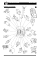
Lotus Service Notes COMPONENT LOCATION DIAGRAM Page 2 Section EMN em196
Lotus Service Notes Section EMN EMN.1 - INTRODUCTION Key 1. 2. 3. 4. 5. 6. 7. 8. 9. 10. 11. 12. 13. to Component Location Diagram Fuel pump Engine coolant temperature (ECT) sensor Water temperature gauge sender (vertical) Crankshaft position sensor Oxygen sensor Intake air temperature (IAT) sensor Oil temperature sensor (VVC only) VVC control solenoids Fuel injector Fuel pressure regulator valve Fuel rail Manifold air pressure (MAP) sensor (VVC only) Ignition coil (std. and VVC shown) 14. 15. 16. 17.
Lotus Service Notes Section EMN paired with 4, and 2 with 3), the spark in the cylinder on the exhaust stroke being 'wasted'. The twin coil pack is mounted on the cylinder block as for standard engines. On VVC engines, the variable valve control mechanism is also controlled by the ECM.
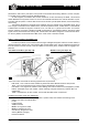
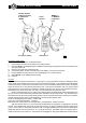
Lotus Service Notes Adaptor harness plugged into DLC & switched to 'MEMS' Power harness Section EMN MEMS 1.9 or MEMS 2J programme card Printer Connect to battery Scanner tool em192 To Connect 'Lotus Check' To connect the equipment, proceed as follows: i). Plug the power harness into the scanner tool and the printer; ii). Insert the MEMS 1.9 (standard engine) or MEMS 2J (VVC engine) programme card into the scanner tool slot, label uppermost. iii). Open the front and rear compartment lids; iv).
Lotus Service Notes Section EMN test. Run a further test to verify the repair. Prog The 'programme' menu is available only on the MEMS 2J card, and allows matching of the engine management and security 5AS modules if one or the other is replaced. At the instant of ignition is switch on, the security 5AS module sends a unique coded signal to the engine management ECM, which must be recognised by the ECM before it will allow the engine to run.
Lotus Service Notes Section EMN EMN.3 - THROTTLE CABLE ADJUSTMENT Before adjusting the cable, first check that the pedal end of the cable is correctly located, and that the cable is correctly routed with no sharp bends or entrapment. Do not attempt to adjust the throttle cable or idle speed by means of the stop screw on the throttle body, which should not be disturbed.
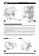
Lotus Service Notes Section EMN Before removing an ECM, first disconnect the battery earth lead before pressing the retaining barb and unplugging the harness connector(s). On standard cars, the MAP sensor is contained within the ECM body, with the sensor hose connecting to a spigot on the underside of the unit. On pre 'boot box' cars, release the three screws securing the ECM to the side panel, and withdraw the unit. On post Sept.
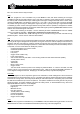
Lotus Service Notes em197 Section EMN Relay module em222a MN.6 - MANIFOLD ABSOLUTE PRESSURE (MAP) SENSOR The MAP signal is fundamental to the calculation of air consumption and fuel calibration. The ECM provides a 5 volt supply and earth path to the sensor, which returns a voltage representing the manifold pressure. On standard engines, the MAP sensor is contained within the ECM and receives a signal from the intake plenum ahead of no.1 cylinder intake tract, via a small bore rubber vacuum hose.
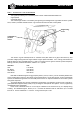
Lotus Service Notes Section EMN EMN.7 - CRANKSHAFT POSITION SENSOR The signals provided by the crankshaft position sensor enable the ECM to determine: engine speed; crankshaft position. The inductive type sensor is mounted by a single fixing into a flange at the right hand rear of the cylinder block, where it protrudes towards reluctor ring machined into the front face of the flywheel.
Lotus Service Notes Section EMN EMN.8 - ENGINE COOLANT TEMPERATURE (ECT) SENSOR The ECM requires a coolant temperature input signal in order to increase fuel delivery and maintain driveability during the cold running and warm-up phase. The signal from this sensor is used for many different parameters within the engine management system to control and switch various components dependent on engine temperature.
Lotus Service Notes Section EMN EMN.9 - INTAKE AIR TEMPERATURE (IAT) SENSOR The intake air temperature (IAT) sensor is fitted into the inlet manifold tract of no.4 cylinder, and is a transducer with a negative temperature coefficient, such that its electrical resistance reduces with increasing temperature. Using this signal in conjunction with that from the MAP sensor, the ECM is able to determine the air consumption of the engine, and adjust the injector pulse width accordingly for correct fuelling.
Lotus Service Notes Section EMN EMN.10 - THROTTLE POSITION (TP) SENSOR The throttle position (TP) sensor is a potentiometer fitted directly to the end of the throttle spindle, and provides the ECM with information on both throttle opening, and rate of change of throttle opening.
Lotus Service Notes Section EMN EMN.11 - IDLE AIR CONTROL (IAC) VALVE The idle air control (IAC) valve is mounted on the intake plenum, and controls an air passage which bypasses the throttle valve. When the pintle of the valve is fully extended, the passage is closed off for a minimum idle speed, but as the ECM commands the IAC stepper motor to withdraw the pintle, a progressively greater amount of air is allowed to by-pass the throttle.
Lotus Service Notes Section EMN EMN.12 - OXYGEN (O2) SENSOR The MEMS system operates a 'closed loop' fuel control system whereby the output signal from an oxygen sensor in the exhaust system is monitored by the ECM, which constantly adjusts the air/fuel ratio to that providing the most efficient conversion of gases by the catalyst. A lean air/fuel ratio causes a high exhaust oxygen content, which reduces the sensor output voltage to the ECM.
Lotus Service Notes Section EMN EMN.13 - CAMSHAFT POSITION SENSOR (VVC versions only) The camshaft position sensor has two functions: i) to provide an engine position reference for the sequential injection; ii) to measure the actual inlet cam period as controlled by the VVC mechanism. The inductive type sensor is mounted on the right hand side of the cylinder head and projects into the cam housing to be in close proximity to a toothed reluctor on the inlet camshaft of no. 2 cylinder.
Lotus Service Notes Section EMN EMN.14 - VVC MECHANISM CONTROL SOLENOIDS The inlet cam period is determined by a hydraulic control unit (HCU) mounted on the right hand front of the cylinder head. The HCU uses two solenoids to operate a spool valve and control a piston and rack mechanism, which outputs from the HCU via a control shaft to the two VVC mechanisms. The ECM energises one solenoid valve at a time to drive the VVC mechanism either towards maximum, or towards minimum inlet cam period.
Lotus Service Notes Section EMN EMN.15 - OIL TEMPERATURE SENSOR An oil temperature sensor is mounted in the top of the VVC hydraulic control unit. The oil temperature is used by the ECM to determine how quickly the VVC mechanism will respond to cam period change commands. To replace the sensor, unplug the electrical connector (brown), and unscrew from the hydraulic control unit. Fit a new seal onto the sensor before inserting and tightening to 15 Nm.
Lotus Service Notes Section EMN EMN.16 - FUEL SYSTEM The fuel system is a high pressure recirculating type, using an 'in tank' submerged 3-stage impeller pump, an in line canister filter, a common fuel rail supplying all four injectors, and a fuel pressure regulating valve controlling the return line to the tank. WARNING: The fuel line between pump and injector rail, and the injector rail itself, contain pressurised fuel both when the engine is running, and after switching off.
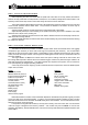
Lotus Service Notes Section EMN Fuel filler neck Filler breather hose Fuel filter Fuel pressure regulator valve Fuel tank Fuel pump Fuel rail Fuel injector Fuel feed line Fuel return line em208 Fuel Pump Switching The fuel pump is controlled by the ECM via the fuel pump relay located in the relay module, and is energised under the following conditions: .
Lotus Service Notes Section EMN function of the regulator is to maintain a constant pressure differential across the injectors at all times. i.e. a constant difference between fuel pressure supplied to the injector, and inlet manifold pressure at the port injector nozzle. By using an intake plenum pressure signal to supplement regulator spring pressure in the valve, the valve is able to regulate fuel supply pressure in accordance with engine load.
Lotus Service Notes Section EMN Push Fit Connectors The fuel rail feed and return hoses are equipped with push fit connectors to allow easy powertrain removal. The feed line connector is colour coded orange, and the return line connector green. Note that the feed line should not be opened without first carrying out the fuel pressure relief procedure detailed above.
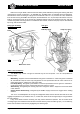
Lotus Service Notes Section EMN Fuel Rail and Pressure Regulator Valve - Replacement Do not attempt to remove the pressure regulator valve from the fuel rail; The valve is supplied only as an assembly with the rail. The fuel rail is removed from the engine complete with the four fuel injectors. 1. De-pressurise the fuel system, and disconnect the battery. 2. Remove the breather hose between intake plenum and cam cover, and the breather hose between the throttle body and cam cover. 3.
Lotus Service Notes Section EMN 8. To remove an injector from the rail, unplug the harness connector, remove the clip, and withdraw the injector from the rail. Discard the two 'O' rings. 9. Before re-fitting the injectors and rail, clean the injector recesses in the rail and inlet manifold, and fit each injector with 2 new 'O' rings lubricated with silicone grease. Fit the injectors into the rail, and retain with the spring clip. 10.
Lotus Service Notes Section EMN Distributor A rotor arm is mounted on a 'D' shaped extension to the rear end of the inlet camshaft, and is retained by a patchlock screw. Always replace the screw, or retreat with Loctite 242. The rotor arm incorporates a suppressor and has a resistance value of 1.25 kohms. The distributor cap is retained by two screws, and is protected from oil contamination from camshaft oil seal leakage by a deflector plate.