
Operating instructions

Copyright © 2012 Draper Inc. Form 220VSLXScissorLift_Inst12 Printed in U.S.A.
Caution:
① Read instructions completely before proceeding.
② Test lift prior to installation. Please Note: Packaging must be removed from lift
before testing.
③ Follow instructions carefully. Installation contrary to instructions invalidates warranty.
④ Do not obstruct operation of Scissor Lift SLX with fi ngers or any object. Serious
injury or damage could result.
⑤ Maximum lifting capacity is 159 kg.
⑥ Scissor Lift SLX is designed to accommodate ceiling suspended equip ment.
Equipment should not be allowed to rest on optional ceiling closure during
operation (refer to section titled “Installing Pro jec tor”).
⑦ Entire bottom of unit must be unobstructed to permit proper op er a tion. Suffi cient
clearance must be allowed below projector or op tion al ceiling closure: 305cm for
Model SLX10, 427cm for Model SLX14, etc.
⑧ Unit must be installed level (use a carpenter’s level).
⑨ Unit operates on 220V AC.
⑩ Verify the show position when testing lift. Make required changes by referring to
adjustment instructions on page 4 of this document.
⑪ Draper does not recommend setting show position at the maintenance/service
position. For example, if you wish to have 244cm Show position, order a lift with at
least a 305cm maintenance position.
CAUTION: Before servicing unit, disconnect hardwired control and any remote control.
Note: Unit has been thoroughly inspected and tested at factory and found to be
operating properly prior to shipment.
Planning
① Based on screen location and projector specifi cations, determine proper
position for projector in stal la tion.
② Confi rm that there is adequate space for installation and operation.
Minimum clear ance above ceiling level varies according to Scissor Lift
model, plus height of projector, optional mounting bracket, optional ceiling
closure, and optional Environmental Air Space Housing.
③ Arrange to provide service access to the unit.
④ Maximum lifting capacity is 159 kg.
As Soon As Scissor Lift Arrives
① Open carton and inspect for damage.
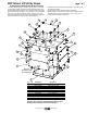
② Locate the following parts:
A. The unit itself
B. Controls
C. Optional equipment: Environmental Air Space Housing, Universal
Projector Mount, closure panel or ceiling fi nish kit (all ship in separate
cartons).
③ Test lift prior to installation. Please Note: Packaging must be removed from
lift before testing.
Installation/Operating Instructions
220V SLX Scissor Lift Video Projector Lift by Draper
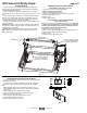
Hanging Unit
Please note: If using Environmental Air Space Housing option, go to
Environmental Air Space Housing instructions on page 3.
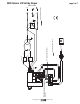
The Scissor Lift may be installed in a variety of ways; recessed above the
ceiling, or sus pend ed below the ceiling. The lift should be supported by four 12.7
thread ed mount ing rods. If ceiling recessed, the entire unit (including the projector)
should set approximately 38 mm above the fi n ished ceiling in its “stored” position.
The threaded rods should pass through the corner mount ing fl anges and be
secured by nuts above and below. The unit should then be guy wired or blocked to
pre vent swing ing.
All installations should observe the following guidelines:
① If installing above a hard ceiling, optional Draper Access Panels are
available to allow access to the unit.
② Installer must ensure that all fasteners and supports are of ad e quate
strength to securely support Scissor Lift and projector.
③ Fastening methods must be suitable for mounting surface, and se cure ly
anchored so that vibration or abusive pulling on unit will not weaken
installation.
Electrical Connections
Unit operates on 220V AC.
Opening the electrical box ex poses ter mi nals for fi eld con nec tions. Unit is shipped
with internal wiring com plete.Wire to connect unit to power supply should be
furnished by in stall er. Con nec tions should be made in accordance with wiring
di a gram, and wiring should com ply with na tion al and local elec tri cal codes. All
op er at ing switches should be “off” before power is con nect ed.
Caution: Make sure electrical supply has been disconnected before
attempting to connect Scissor Lift to electricity.
Scissor Lift should be operated and checked prior to installing pro jec tor and/or
optional ceiling closure.
Low Voltage Control Switch shown below comes with 22.8 meters of cable and
should be plugged in to Control Panel on top frame of lift for control of the "Closed"
and "Show" positions. Momentary Key Switch shown below comes with 22.8
meters of cable and should be plugged in to Control Panel on top frame of lift for
control of the "Service" position.
®
If you encounter any diffi culties installing or servicing your Scissor Lift, call your dealer
or Draper, Inc. in Spiceland, In di ana, 765-987-7999, or fax 765-987-7142.
④ Unit should be level, with weight shared more or less equally by all four
threaded mount ing rods.
⑤ Bottom of unit must be unobstructed after installation. Suffi cient clear ance
must be allowed below projector or optional ceiling closure.
⑥ Do not use unit to support adjacent ceiling, light fi xtures, etc.
⑦ Do not complete the ceiling below unit until electrical connections have
been completed and unit has been operated successfully.
⑧ We recommend that safety cables be attached to the Scissor Lift SLX for
added security (a sound in stal la tion practice with overhead equipment).
⑨ When the Scissor Lift SLX is to be installed in “other space used for
environmental air” the optional environmental air space housing must
be installed per instructions to isolate the lift from the “other space
used for environmental air.”
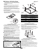
Operation
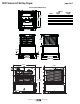
Before operating or testing the unit, make sure the packaging has been
removed from the unit. This can be accomplished by removing the eight screws
(four per side) holding the packing frame to the lift. Once the packaging is all
removed, operate the lift in the "up" direction, so the lift's control encoder will
recognize it's "home" location. Until you do this, the Down function will not work.
You must also do this if the Scissor Lift ever loses or is disconencted from
the power.
When unit is fi rst operated, be cautious! If unit fails to operate properly, press
“off” and recheck elec tri cal con nec tions before pro ceed ing. Cycle unit down and up
several times to confi rm sat is fac to ry operation.
Caution: Do not pull on or touch safety belt when unit is in motion. If belt
locks, the cables will unspool.
Caution: Obstructing bottom pan may cause cables to unspool.
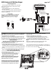
Standard Single Station Low Voltage Control (See Fig. 1) (CE Approved)—
One three-button switch with “up”, “down”, and “off” buttons. Lift starts up or
down when ap pro pri ate button is pressed, and may be stopped by pressing “off”
button. Factory set limit switch es stop lift automatically when pro jec tor is in “show”
position. One momentary key switch lowers lift from “show” to “service” position.
Optional Multiple Station Control (Not CE Approved)—Optional, moves lift from
“stored” to “show” position only. Each switch ing station has a three-button switch
with “up”, “down”, and “off” buttons. Lift starts up or down when ap pro pri ate button
is pressed, and may be stopped by pressing “off” button. Factory set limit switch es
stop lift automatically when pro jec tor is in “show” position.
Optional Key Operated Switch (Not CE Approved)—If ordered, the standard
LVC-S can be replaced with a second single station, momentary key-operated
three position (up/off/down) switch. Multiple Station Control re quired for this option.
Moves lift from “stored” to “show” position only.
Optional Infrared or Radio Frequency Remote Control (CE Approved)—If
ordered, a three-button transmitter is provided, with “up”, “down”, and “stop”
buttons. Unit starts up or down when appropriate button is pressed, and may be
stopped by pressing “off” button. Factory set limit switches stop unit au to mat i cal ly
when projector is in “show” po si tion. Only controls "show" and "stored" positions.
Optional RS232 Control (CE Approved)—For Serial communication an R2D7
Serial Communications Interface is optionally available.
Low Voltage Trigger (CE Approved)—Input provided for Low Voltage Trigger from
projector (see diagram on page 4).
Please Note: Scissor Lift SLX must be installed in accordance with the requirements
of the Local Building Codes, the Canadian Electrical Code (CEC), CAN/CSA
C22.1 and the National Electric Code (NEC), NFPA 70, as required. An appropriate
disconnect device shall be provided as part of the building installation.
UP
OFF
DOWN
UP
DOWN
OFF
LVC-S SP-KSM
Up & Show
Service
Figure 1
Caution: Beware
of pinch points
These Installation/Operating Instructions are available in the offi cial language of the
country where you purchase the product. Please contact your distributor to request a
copy.
Vous pourriez demander les instructions d’installation et d’opération traduises dans
la langue offi cielle du pays ou vous achetez le produit. Veuillez demander à votre
distributeur.
Die Gebrauchsanweisung für Installation und Konstruktion sind in der offi ziellen
Sprache des Landes, indem Sie das Produkt gekauft haben, vorhanden. Fragen Sie die
jeweilige Verkaufs-Abteilung.