Draper Inc., Motorized Flexshade Handbook Table of Contents 1. Introduction To Motorized Shades .........................................................................................................................................................................................2 2. How to Measure, Recommendations and Tips ......................................................................................................................................................................3 3.
Introduction to Motorized Shades Motorized shades can be a big profitable opportunity or a big pain depending on how you go about it. Being educated on the product before handling or installing it will greatly increases your chances at having a successful, profitable install. This is why we at Draper, Inc. have created this motorized document. We hope this gives you more help on understanding and installing your motorized shade jobs. Motorized shades offer your customer many benefits.
How to Measure for Draper Shades FlexShades are custom fabricated for each opening, and must be measured accurately. Determine the area to be covered, and decide where brackets or endcaps will be attached. Be careful to allow for any irregularity which will interfere with the proper operation of the unit (i.e. handles, irregular trim, locks or opening not square and plumb). Inside Mount 1.
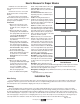
Terms In trying to understand motorized shades, it is important to know certain terminology. These terms used by Draper, electricians, and others when discussing motorized cover how power brought to the shades, wire size used, control types used, and more. High Voltage or Line Voltage—These terms refer to 110 or greater voltage. In the US and Canadian markets, most high voltage shades jobs are supplying 110 to 120 VAC to the motors. This type of voltage will most likely be in conduit.
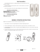
Radio Motor Transmitters There are several types of radio motor transmitters, and here is a listing of them and when you need them. A radio motor can learn up to twelve different transmitters. - Single Channel Transmitter, C072.011—This is a one channel remote for operating one shade or one group of shades. It is able to send an up, stop, down, and intermediate stop command. - Four Channel Transmitter, C072.
Telis Transmitters Telis hand-held radio transmitters are compatible with RTS Motors and external RTS receivers such as Centralis or HRC-RF. Each Telis transmitter can operate any number of motors or receivers. Each motor or receiver will memorize up to 12 transmitters. The four channel transmitter can be used for group and individual control of window treatments. MECHANICAL SPECIFICATIONS Overall Dimensions: L: 5¼ in. W: 15/8 in. D: 11/16 in.
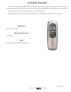
20-Channel Transmitter This is a 20-channel, Composio, handheld transmitter for Radio Motors. It has an interactive screen for setting functions. It also has a dock for placing the transmitter on the wall. The Composio gives one greater control over large groupings of Radio Motors than other transmitters. The Composio cannot be used to program limits like the 1 and 4 channel transmitters. Programming instruction for the transmitter come packaged with it.
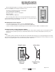
DECORA RTS SWITCH Operating Instructions The Decora RTS Switch (single or four channel) is a wireless radio transmitter compatible with all the RTS MOTORS, and externally mounted RTS receivers. - Commands are transmitted by radio waves at 433.42 MHz. - Power: 3V lithium battery, CR 2430 type - Operating temperature: +5 C/41 F to +40 C/104 F - Range: Up to 65 Ft.
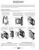
DECORA RTS SWITCH Mounting Instructions The special low-voltage bracket is specifically designed to mount the Decora RTS wall switch next to an existing Decora light switch with an electrical box already behind the drywall. This bracket differs from other off the shelf low-voltage brackets because it is offset to one side. This allows a double gang Decora style cover plate to fit over both switches without installing a double gang electrical box behind the drywall.
Radio Remote Control Motor Programming Instructions When you receive a radio remote control motor from Draper, Inc., the motor has no programming on it so it must be learned and programmed to work on the transmitter that you have at the job. Here are the initial programming instructions. ➀ Connect power to 1 motor. Select the transmitter/channel to which you plan to learn the motor. Press and hold the UP and DOWN buttons at the same time until the motor jogs, then release.
Inteo Chronis RTS Timer Quick Reference Guide Programming the Chronis: Programming the Chronis depends on the item it will be controlling. For instance: Centralis, Eolis, Altus. Follow the specific programming instructions for each item it will be controlling. The programming button of the Chronis is located under the switch cover, right above the display. “Prog” will appear on the display as you press it. On/Off: Turn the Chronis Off by pressing the “+”.
Inteo Light Sensor Installation Guide Together with the Chronis Uno L, Chronis IB L, Chronis RTS L, Chronis Comfort RTS, Chronis Comfort IB and Chronis Comfort UNO, the brightness sensor can be used to operate your roller shutters and venetian blinds in relation to the amount of light. These control units have an integrated automatic solar control unit (L = light control) that automatically creates shadow if the sunshine is too strong.
2.2 Automatic solar control unit with a Chronis Comfort Switching the automatic solar control unit on / off. The automatic solar control is activated when the UP switching time is reached and de-activated when the DOWN switching time : 1432 is reached. This means the following in normal use: the automatic solar control unit is switched on during the day and off at night. ( 21 : 27 When it is on, a is shown in the display. You can switch the automatic solar control unit on or off manually during the day.
2.4 Automatic dusk control unit with a Chronis Comfort (not with Chronis Comfort RTS) Switching the automatic dusk control unit on / off: You can switch the automatic dusk control unit on or off manually. The factory setting for the automatic dusk control unit is ON. To switch the automatic dusk control unit off: 1 3 S 14 :32 C 21:27 2 2 s. IN CLOC 0.5 s. 14:32 * SEnS 0n b 06 * d 00 OFF SEnS 0.5 s. 4 b 00 0.5 s. 2 s. * 0.5 s.
RTS Dry Contact Interface Operating Instructions The RTS Dry Contact Interface can be used to communicate between home automation or other third party systems and RTS Motors and Inteo line of controls. BatteryHolder RED BLACK GREEN WHITE ProgrammingButton NOTE: Please consult RTS Motor Instructions for specific product details. 1 Place the RTS Motor in Programming Mode as described in the individual product operating instructions.
Universal RTS Interface II DESCRIPTION The addressable Universal RTS Interface II (URTSI II) can be used to communicate between home automation or other third party systems and RTS Motors and controls. It is capable of individual or group control, and can be operated via infrared remote, RS232 and RS485 serial communication. Once an input is activated, an RTS radio command is sent to the automated window treatment.
OPERATION A. INITIAL SETUP 1. Connect a 9v DC transformer (included) to the receptacle on the back of the control box. The LED will light green to indicate power. 2. Be careful not to mount or enclose Interface on or in metal, as this may effect radio reception. 3. Set the RTS Receiver or motor into its Programming Mode. Refer to the installation instructions of the relevant RTS receiver or motor for this procedure. NOTE: for initial programming provide power only to the motor or control being programmed.
RS232 to RTS Interface with X10 Compatibility Description The RS232 to RTS Interface is a 16-channel RTS transmitter that enables third party home automation systems to directly control Somfy’s line of RTS motors and controls. The interface also includes X10 compatibility for direct control of RTS product from an X10 powerline system. The interface plugs into a standard 115 VAC electrical outlet.
RTS Repeater Description The RTS Repeater can be used in installations to extend the range of the standard Radio Technology signal. It will receive the signal from a Telis or similar device and retransmit the signal to a RTS compatible motor or receiver. Part Number 1810686 Mechanical Specifications Operating Procedures Overall Dimensions: L: 4 in. W: 2¼ in. H: 13/8 in. Frequency: 433.42MHz Range: 60ft Simply plug the receiver into any 120v AC outlet.
Radio Motor Accessories In the previous section radio motor transmitter information was given. This section talks about the accessory parts that come with Radio Motors. We have broken down the accessories and to which motor that they belong. Battery motor accessory is: Battery Wands- Wands are included with new battery motor shades. The battery wand replacements are part no. C105.005. There are now reloadable AA battery wands available and part no. is TBA.
Battery Wands Battery Wands are the power source for battery motors. Wands do come with every motor purchased. Replacement wands can be purchased if needed. Draper only uses the 12V double battery wand or reloadable wand. Battery life is highly variable depending on the shades size and number of operations that one runs. Typically, the life is 1 to 3 years. Another thing other than shade size and operation which may reduce battery life is RF interface.
Plug-In Transformers These transformers are for supplying 24VDC to our low voltage motors. There are 6 types of transformers, but the numbers and type of these transformers are subject to change at any time without notice. These transformers are not special to window shade motors and you may source a transformer which meets the power requirements needed on your own. If you want something different than we carry, we recommend that you do this.
DIN-Rail Transformer—DR-120 Features: - AC input range selectable by switch - Protections: Short circuit/Overload/Over voltage/Over temperature - Cooking by free air convection - Can be installed on DIN rail TS-35/7.5 or 15 - UL 508 (industrial control equipment) approved - LED indicator for power on - 100% full load burn-in test - Fixed switching frequency at 55KHz - 3 years warranty SPECIFICATION MODEL DC Voltage Rated Current Current Range Rated Power Ripple & Noise (max.) Note 2. Voltage Adj.
DIN-RailTransformer—DR-120—Page 2 Page 24 of 120 www.draperinc.
DIN-RailTransformer—DR-240 Features: - Universal AC input/full range Built in active PFC function Protections: Short circuit/Overload/Over voltage/Over temperature Cooking by free air convection Can be installed on DIN rail TS-35/7.5 or 15 UL 508(industrial control equipment/approved LED indicator for power on 100% full load burn-in test Fixed switching frequency at 100KHz 3 years warranty SPECIFICATION MODEL DRP-240-24 24V 10A 0 – 10A 240W 80mVp-p OUTPUT 24 – 28V ±1.0% ±0.5% ±1.
DIN-RailTransformer—DR-240—Page 2 Page 26 of 120 www.draperinc.
DIN-RailTransformer—DR-480S Features: - AC input range selectable by switch - Built in passive PFC function compliance to EN61000-3-2 - High-efficiency 89% and low dissipation - Protections: Short circuit/Over Load/Over voltage/Over temperature - Cooling by free air convection - Built-in constant current limiting circuit - Can be installed on DIN rail TS-35/7.
DIN-RailTransformer—DR-480S—Page 2 Page 28 of 120 www.draperinc.
10 Motor Power Panel The 10 motor power panel is for powering the Low Voltage Radio Motor. It is not required, but it does make installation easier. A transformer is still needed, and it will feed power to the panel. You can parallel wire the motors directly into the power feed off the transformer. This, however, makes connecting and disconnecting the motor from power to program it difficult and cumbersome.
Centralis Receiver Inteo Remote Control The Centralis Receiver is a single motor control designed for residential use. It includes an integrated radio receiver, plus input terminals for an optional low voltage switch. Using the Telis Transmitters, it is possible to operate the controls individually or in groups. Two user-defined intermediate positions can be programmed. This control is packaged in a weatherproof enclosure and includes watertight strain-relief fittings for wires entering the box.
Toggle Switch (SP/DT) and Princess Rocker (DP/DT) The maintain toggle switch (SP/DT) is the standard switch which is sent with shades. Maintain switches when flipped stay in the up or down position for one to walk away while the shade moves. Ivory is the standard color (Part 121101), but one can get it in white (Part 121102). The momentary toggle switch is an alternate switch which one can have in place of the maintained. They come in ivory (Part 121103) or white (Part 121104).
KS-3 3-Position Key Switch ® Technical Data Sheet Part Numbers: 121018—Maintained 121022—Momentary USES: The KS-3 replaces the standard single-station control switch for all products (screens, shades or projector lifts) where the directional functions (Up and Down) need to be combined with the security of a key switch. COMPATIBILITY: KS-1 Power Supply Key Switch. The KS-3 is intended as the sole control station, and cannot be used as a multiple station control.
MS-3R, MS-4R Multiple-Station Control ® Technical Data Sheet Part Numbers: 121002—MS-3R and MS-4R 121025—Additional MS-4R USES: The MS-3R and MS-4R are 3- and 4-wire versions of the same switch, used for controlling one screen from multiple locations, using the motor’s voltage (115V or 220V). MS-4R is the first control station in a series of stations. It is also the intermediate control (s) in the case of three or more stations. The fourth wire passes electricity to the next switch in the series.
Motor Pigtails and Disconnects Motor Pigtails are a standard of 6’ with a 18 gauge 3 conductor with a ground on 4 wire motors. It is a 18-2 with 3 wire motors. The pigtails do come in longer lengths up to 24’. 3 wire pigtails also can come with an optional 3 prong plug (see page 20). All motor pigtails are not plenum rated. They are a PVC jacketed cable with a diameter of 5/16".
Isolating Relays The isolating relay (ISO relay) prevents feedback between motors and allows multiple motors to run off a 120V switch. The switches that Draper supplies are 15A so twelve standard motors are able to run off one switch with isolating relays. To further help you decide if isolating relays are right for you, here are some conditions in which you would use them: - You want to run multiple shades at one time, together off of one high voltage wall switch.
Wiring Instructions ™ Isolating Relay by Draper Part Number C157.012 Electrical Specifications Please Note ➀ Make sure power is disconnected before installing controls. ➁ This product is designed to be a job site rescue device by allowing multiple motors to be connected to one motor control or switch and provides group control of these motors. Each motor must have its own ISO Relay.
IntelliFlex™ GC4 The GC4 (group control 4 motors) prevents feedback between motors and allows multiple motors to run off a 120V switch. The switches that Draper supplies are 15A so twelve standard motors or three GC4' s are able to run off one switch with GC4' s. To further help you decide if a GC4 is right for you, here are some conditions in which you would use them: - You want to run multiple shades at one time, together off of 1 high voltage wall switch.
Part Number C156.058 Wiring Instructions ™ GC4 Control by Draper Electrical Specifications Please Note ➀ Make sure power is disconnected before installing controls. ➁ This product allows up to four motors to be connected to one motor control or switch and provides group control of these motors. Make sure the total FLA of all motors grouped together does not exceed the load carrying capacity of the switch or motor control being used.
IntelliFlex™ SC1 The SCI (smart control 1 motor) gives intelligence to standard motor. This intelligence allows you to group shades and run them from low voltage switching. You may run the SC l' s from a number of IntelliFlex inputs. Here are some conditions in which you would use them: - You want to control shades individually and as a group. You want to have up to four preset intermediate stop locations. You want to reduce wiring by remotely locating the controls near motors.
Wiring Instructions ™ SC1 Control by Draper Please Note Part Number C156.065 Electrical Specifications ➀ Make sure power is disconnected before installing controls. ➁ SC1 has a rated switching capacity of 6 amps. ➂ SC1 is a line voltage control, designed to operate one motor. Activation by Low Voltage input commands. If you want to switch two or more motors, ISO relays must be installed in the circuit. ➃ SC1 is electrically “hot” on the back of the circuit board. INS-SC1 (Draper Part Number C199.
IntelliFlex™ SGC4 The SGC4 (smart group control 4 motors) gives intelligence to standard motors. This intelligence allows you to group shades and run them from low voltage switching. You may run the SGC4' s from a number of IntelliFlex inputs. Here are some conditions in which you would use them: - You want to control shades as a group. You want the most cost effective group control that works with low voltage switching. You want the controls in an electrical enclosure and to be a UL assembly.
Part Number C156.059 Wiring Instructions ™ SGC4 Control by Draper Electrical Specifications Please Note ➀ Make sure power is disconnected before installing controls. ➁ SGC4 is a line voltage control, designed to operate up to 4 motors as a group, activated by Low Voltage input commands. ➂ SGC4 enclosure is 8" x 8" x 4". ➃ Main Disconnect and Branch Circuit Protection provided by installer. ➄ Maximum surrounding air temperature 50° C.
IntelliFlex™ SPGC4 The SPGC4 (smart programmable group control 4 motors) gives intelligence to standard motors. This intelligence allows you to group shades and run them from low voltage switching. You may run the SPGC4' s from a number of IntelliFlex inputs. Here are some conditions in which you would use them: - You want to control shades individually and as a group. You want to have up to four preset intermediate stop locations. You want the controls in an electrical enclosure and to be a UL assembly.
Wiring Instructions ™ SPGC4 Control by Draper Electrical Specifications Please Note ➀ Make sure power is disconnected before installing controls. ➁ SPGC4 is a line voltage control, designed to individually operate 4 motors, activated by Low Voltage input commands. ➂ SPGC4 enclosure is 8" x 8" x 4". ➃ The Main Disconnect and Branch Circuit Protection shall be provided by installer. ➄ Maximum surrounding air temperature 50° C. ➅ Use copper conductors rated 75 degrees Celsius or higher only, 1812AWG.
IntelliFlex™ Inputs We have many different low voltage input devices for controlling shades through IntelliFlex. Here is a listing and brief description of each input available to you. OS CL OP OS CL OP EN IR control E EN L E AL 8 1 9 2 10 3 11 4 12 OP ST 5 6 7 - IR control- This is an IR eye plugged in an SC1, SGC4, or SPGC4 to receive IR remote commands. - RF control- This is an RF receiver plugged in an SC1, SGC4, or SPGC4 to receive RF remote commands.
SC1, SPGC4 or SGC4 From "A To "A ux" (can a ux" "Eye t lso be o if "Eye Aux" not in " por t Splitter use)* Eye Eye Main Aux 4 6 8 3 5 7 Please Note: Eye Eye Main Aux Splitter To Motor (s) To Motor (s) To Motor (s) PSSW RR24 RF Receiver (-17 mA) RF Signal to Receiver Sun Sensor Eye Sun Sensor (-13 mA) Copyright ©2007 Draper Inc. Form IntelliFlex-InputDeviceConfig07 Printed in U.S.A. PC/ Home Automation 8 7 Any input device may be connected to any available Eye port.
Installation Instructions ™ IR Remote Control by Draper Caution: ➀ The IR Receiver Eye must connect to an "Eye" Jack on an SC1 or Splitter. If it connects to a Splitter, then the Main Jack of the Splitter must connect to the "Eye" Jack of an SC1. ➁ Main Jack on splitters connects to Eye Jack on SC1. ➂ Any Aux Jack can be connected to any Aux or Eye Jack. ➃ Never connect any two Eye Jacks together.
IntelliFlex™ IR Remote Control by Draper Page 2 of 2 Installing IR Eye Only into J-Box IR Eye Only Optional Cable Accessories Splitter 1" flat head screws in J-box Infrared Cover fits in Decora Plate IR Codes IR wavelength is 950 nm. Light is modulated at 38 KHz with 1/3 duty cycle. An on pulse must be at least 158 µseconds (µs) long (6 cycles) and should not be longer than 448 µs (17 cycles).
Installation Instructions ™ RF Remote Control by Draper ➀ The Radio Frequency receiver must be connected to an Eye Jack on an SC1 or splitter. ➁ Mount receiver with the antenna pointing up. ➂ Do not mount receiver on or near a metal surface. ➃ Each RF receiver must be “trained” to “hear” each transmitter before it will work. ➄ Each receiver can “learn” to “hear” up to five different transmitters. Installing the Receiver Connect the receiver to the Eye Jack on an SC1 or splitter (see Fig. 1).
IntelliFlex™ RF Remote Control by Draper Page 2 of 2 A Note on Interference Optional Cable Accessories This equipment has been tested and found to comply with the limits for a class B digital device, pursuant to part 15 of the FCC Rules. These limits are designed to provide reasonable protection against harmful interference in a residential installation.
™ Wall Switch by 2 button, 1 channel—horizontal switch for 1 shade or group of shades 2 button, 2 channel—sequencing switch for 1 shade or group of shades 3 button, 3 channel—sequencing switch for 1 shade or group of shades 3 button, 1 stop—vertical switch for 1 shade or group of shades 121105—BUS command 121106—Dry Contact 121107—RF (requires 1 RFTM p/n C072.022, ordered separately) 121108—BUS command 121109—Dry Contact 121110—RF (requires 1 RFTM p/n C072.
Page 2 of 2 IntelliFlex Wall Switch by Draper Programming IntelliFlex Switch Hardwired “Bus” Command Switch Dry Contact: Does not have a Bus connection, and is not programmable. It is somewhat configurable, based on how it is connected—it must be connected directly to each device it is controlling. Bus: Programming requires physical contact with the back of the switch. This allows programming of which button sends which command, and other options.
Installation Instructions ™ Wall Switch by Draper RF “Bus” Wall Switch Program Button "Eye" Jack “Bus” Wall Switch Program Button "Eye" Jack Dry Contact Wall Switch (Switch Front/ Button Map) Please Note: This drawing indicates all possible connection and button locations. Your switch may not have the same number of buttons or connections, but their locations will be consistent with these "maps." Compare your switch with these diagrams, and wire the buttons and connections on your switch accordingly.
Page 2 of 2 IntelliFlex Wall Switch by Draper Programming IntelliFlex Switch Dry Contact: Does not have a Bus connection, and is not programmable. It is somewhat configurable, based on how it is connected—it must be connected directly to each device it is controlling. Can be connected to a Bus via PSI60. RF: Battery operated. Programming the RF switch requires physical contact with the back of the switch, and allows programming of which button sends which command, along with other options.
Installation Instructions ™ R2D7 RS232 Professional Integration Interface by Draper To Bus System 7 (or to RF Transmitter) To Bus System 6 To Bus System 5 To Bus System 4 Please Note ➀ Includes free “GUI” software capable of scheduling timed events and global alignment positioning of shades. ➁ For information on programming and operation, see IntelliFlex Programmer instructions available at www.draperinc.com. ➂ This input device can be used with SC1, SGC4 or SPGC4.
Installation and Programming Guide Sun and Wind Sensor V1.l and Sun Sensor Switch V4 by Draper, Inc. Connect to the Sun and Wind Sensor as shown: All wires labeled “Common” are connected together and are electrically the same as the Black wire on the Bus; any common wire can be used in place of any other common wire in the drawing. The Light Sensor may be connected to the spring-loaded connector or to the sensor jack. For best results, use only one of the Light Sensors shown.
SUN AND WIND SENSOR V1.l and SUN SENSOR SWITCH V4 by Draper Page 2 of 9 The Program Mode LED must now be lit solid GREEN, if it is not, repeat the above steps. The SUN AND WIND SENSOR will automatically exit program mode after 20 seconds if no commands are received. If programming commands started via an eye on the BUS, then BUS must be used to complete this programming. The same goes for the Sun Sensor Switch jack. While in programming mode, commands seen on either jack are repeated to the other.
SUN AND WIND SENSOR V1.l and SUN SENSOR SWITCH V4 by Draper Page 3 of 9 Sun Actions: This Sheet uses "#" for this unit's accessory number - new units will use a 1 where the # is (ALL also works). 2 The LED will turn RED then back to GREEN to indicate you are in a multi-button sequence. This means whatever "button" you want to "send" at the selected event, STOP means ignore the event. 4 Completing this sequence automatically turns off user selection of sun "level" via Sun Sensor Switch.
SUN AND WIND SENSOR V1.l and SUN SENSOR SWITCH V4 by Draper Page 4 of 9 Defaults: Sun sensor timing = 10 minutes, low sunrise at 68 with increment of 3, low sunset at 48 with increment of 3. User level selection is allowed and is set to high, Summer and Winter Actions =No Intermediate Positions on Sun (as shown in "Sun Intermediate Stops"), Sun Sensor not disabled via a channel, No channel to switch between Summer & Winter, Sun Sensor always uses Summer Actions.
SUN AND WIND SENSOR V1.l and SUN SENSOR SWITCH V4 by Draper Page 5 of 9 Three Intermediate Positions on Sun, use default settings (S+7+7 > C# > C10 > 08): Four Intermediate Positions on Sun, use default settings (S+7+7 > C# > C10 > 09): Sun Thresholds and Levels User selection of "level” using Sun Sensor Switch: If the user presses the appropriate buttons on the Sun Sensor Switch to set the Sun threshold, all thresholds are moved up or down appropriately.
SUN AND WIND SENSOR V1.l and SUN SENSOR SWITCH V4 by Draper Page 6 of 9 SUN assuming fixed levels The sun sensor is capable of sending independent bus commands as a result of each of the 5 sunrise and sunset events, and the thresholds may be adjusted individually. However, once this capability is enabled, the user selectable "level" is disabled. The Sun Sensor Switch is simply a display of sun levels in this case. Setting any sun event to a custom value (S+7+7 > C# > C1 or C2 > Cx . . .
SUN AND WIND SENSOR V1.l and SUN SENSOR SWITCH V4 by Draper Page 7 of 9 Press an open or close command on the IR transmitter and make sure the appropriate action happens on the SC1 system. Draper Sun Switch (DSK) (optional): This Sheet uses $ for this Sun Sensor Switch's accessory number - new units will use a 6 where the # is (ALL also works). 14 This means open + close, all others are turned off 15 This means whatever “button" you want to "send" when the button is pushed.
SUN AND WIND SENSOR V1.l and SUN SENSOR SWITCH V4 by Draper Page 8 of 9 NO intermediate positions on Sun: High (2nd from the top) and medium-high (3d from the top) buttons. Sunrise & Sunset events will be set as shown in "Sun Intermediate Stops'' section above under “No Intermediate Positions." Selected Sun level is set to high. The SC1s intended to be controlled by the SUN AND WIND SENSOR are NOT affected by this action and must be programmed separately.
SUN AND WIND SENSOR V1.l and SUN SENSOR SWITCH V4 by Draper Page 9 of 9 You cannot program the Sun Sensor Switch using S+7+7 CloseALL unless you are using a splitter etc. The CloseALL command is interpreted by the SUN AND WIND SENSOR as "'enter program mode" - and it turns on its GREEN LED and awaits programming commands -and the Sun Sensor Switch goes into program mode, and they do not use the same programming steps.
Installation Instructions LCD Timer by Draper ➀ The timer acts as a “normally open” (NO) switching device. ➁ The timer may be set to deliver up to seven (7) On/Off setting pairs. Each setting pair can be set to activate: everyday, once a week, every weekday, or weekends only. ➂ When connecting to SC1 or PSI60, polarity does not matter CAL CLK PGM AUTO RAND MAN OFF AM PM 12:00 d MO TU WE TH FR SA SU ON + ➀ The timer acts as a “normally open” (NO) switching device.
IntelliFlex™ LCD Timer by Draper Page 2 of 3 Programming/Setting the LCD Timer NEXT/ ON/ OFF Resetting the timer Switches between ON and OFF settings when programming the time. Confirms program entry and advances timer to next selection. Press the reset and the “Next/On/Off” buttons at the same time. Release the buttons and wait for “12:00” to start blinking. Setting the calendar Press the mode button one time. “Cal” will appear in the top left corner.
IntelliFlex™ LCD Timer by Draper Page 3 of 3 Page 67 of 120 www.draperinc.
Installation Instructions ™ PSI60 Bus Command Converter by Draper ➀ Make sure power is disconnected before installing controls. ➁ Make sure AC Amperage of any wall switches are not exceeded, and that wires are large enough for loads. ➂ All AC motor controls are UL approved. For use with X-10 controls: ➀ SPDT Mode: Program to factory default, and connect 2 universal modules in momentary mode (one between open and common, the other between close and common.
® Introductory Overview The IntelliFlex Control System is an intelligent yet simple package of controls and input devices that provides a single source opportunity to install any type of motor controls on a range of products and have them all work together seamlessly in an installation. The heart of the system is the SC1 (see Fig. 1), a single motor switching relay with a built in microprocessor. Think of the SC1 as being two different switches in one.
® Controls Planning Sheet by Assign Group Numbers: Stop Enabled (A or B) Open Close Stop Open Close Stop Open Close Stop Open Close Group ComComEn- Group ComComEn- Group ComComEn- Group ComComChan- mand mand abled Chan- mand mand abled Chan- mand mand abled Chan- mand mand nel Position Position (A or nel Position Position (A or nel Position Position (A or nel Position Position (%) (%) B) (%) (%) B) (%) (%) B) (%) (%) Main Channel Assignment* Shade 1 Shade Location Shade 2 Shade 3 Shade 4 1st Group
SC-1 Quick Reference Guide (OS firmware version 3) by Draper This Sheet uses # for the receiver’s main channel number - new units will use a 1 where # is. Note that # can also be ALL if you want to program several receivers S = Stop C = Close 0 = Open LED on blink Reset EVERYTHING to factory default S+7+7 O ALL hold 5 sec.
Page 2 of 2 SC-1 Quick Reference Guide by Draper Defaults: Main Channel = 1, Group Channels 1-6 = off, no sequencing action channel, Maintained Motor Action, Standard Motor Direction, Act on ALL buttons from Transmitter, Standard action on the group buttons, Standard IR Release Time, Do not Stop On Transmitter Button Release, Deadbeat Counter Disabled, Demo mode Off.
Intelligent (ILT) Motor Overview The Intelligent Motor is designed to offer the sophisticated, diverse control of a window shade. The motor contains a controller inside of it. This means that there are two wires exiting the motor head. One wire is for power. It is a high voltage wire which will supply power to the motor at all times. The other wire is low voltage. This wire will connect to control and operate the motor.
ILT Switch and Limit Sets The ILT switch has a modular connector on the back to plug in the Intelligent Motor, once the motor is connected then limits can be set and the shade can be operated. The ILT switch fits into a single gang box with a decora face plate and is flush with the plate. Setting Limits on an Intelligent Motor Shade are as follows: ➀ Connect the ILT switch to motor via the modular cable port. The cable connectors MUST NOT be crimped in reverse as with standard telephone cable.
ILT Dry Contact Interface Wiring Diagram To ILT Motors The ILT Dry Contact Interface will operate up to four ILT motors as a group from an external device such as a home automation system. ➀ To activate an UP command, a momentary contact closure is required between the UP and COM terminals. C U O P +5v M D W N ➁ To activate a DOWN command, a momentary contact closure is required between the DWN and COM terminals. ➂ To activate a STOP command, a momentary contact closure is required.
Draper Digital Network IP Interface The Draper Digital Network IP Interface is a serial device server used to connect the RS485 SDN BUS consisting of ILT2 motors and control devices to a managed LAN network. The firmware of the IP Interface is remotely upgradeable over the Internet. The SDN IP Interface contains an internal Web server with configuration software that is accessed via any standard Web browser. The IP Interface is compatible with both the PC and the Mac platforms.
Draper Digital Network The Draper Digital Network which is run from the IP interface mentioned on the previous page is programmed through a series of actions. These actions and items used to program the system are constantly changing so it is required to contact Draper before programming a Digital Network. Here are the items that you will currently need to program a Draper Digital Network. 1 2 3 4 5 6 7 Laptop Computer RS 485 adaptor cable- Draper can direct you where to buy.
The next part of the install is to program the group addresses. For this you will have to check several different things: 1 Are the low voltage lines from the motors going to an ILT Tap? Are the ILT Taps connected together with Cat 5? Do you have a 12V trans former feeding power to every 40 ILT Taps? 2 You may use a splitter to put up to 3 motors in an ILT Tap, but a motor cannot have more than 30’ of cable between it and an ILT Tap even with a splitter.
RS485-ILT Link DESCRIPTION The RS485-ILT Link will enable third party communication to Somfy’s line of intelligent (ILT) motors, and for programming and receiving addresses from intelligent motors. MECHANICAL SPECIFICATIONS Overall Dimensions: L: 31/8 in. W: 25/8 in. H: ¾ in.
Draper Digital Network—Smart Switch Description: The Smart Switch is a control device which outputs the SDN protocol over RS-485, providing digital control of the Digital Network. The Smart Switch allows the SON to function as a stand alone natural lighting control system and can be fully customized though the SON Smart Switch Configuration Software. The Smart Switch is available in 3-button and 6-button versions which can be located anywhere on the Somfy Digital Network.
110-120V Standard and Quiet Motorized Flexshade Motor Mounting Bracket Small C002.058.49 Large C002.051.49 Motor End Cap Small C002.571 Large C002.677 Idler Gudgeon Assembly 2” C052.041 3” C052.064 End Cap Cover Retainer Clip C014.013 End Cap Cover Available in black, white, ivory, bronze or clear anodized finish Idler End Cap Small C002.572 Large C002.676 Idler Mounting Bracket Right Small C002.062.49 Right Large C002.055.49 Left Small C002.063.49 Left Large C002.056.
Standard 4-Wire Motors Altus Motors ILT DC Flexshade Flexshade 2 Flexshade/Export Flexshade 2/Export ® Standard motor 506S2RH 510S2RH 504S2RH-ST 506G 506S2PA 510S2PA 506S1RH 510S1RH 503S1RH-ST 506S1PA 510S1PA 660R2 506S2RH-RTS 510S2RH-RTS 504S2RHST-RTS 506S2-RTS 510S2-RTS ST-30 BA-RTS 506S2ILTRH Y Y Y Y Y Quiet Motor 120 120 120 120 120 120 230 230 230 230 230 120 120 120 120 120 120 24DC 12DC 120 Volts 0.95 1.3 0.95 0.9 0.95 1.3 0.95 0.95 1.3 0.95 1.3 2.5 0.95 1.3 0.95 0.95 1.3 1.8 n/a 0.
Motor Name: 506S2RH Torque in Nm: Volts: 120 6 Amps: .95 RPM: 38 Parallel Wire: No Roller Diameter Choices: 2” aluminum, 2” steel, 2 1/8” steel, 3” steel, 3 1/8” steel Product (s) Used In: Motorized Flexshades, Lightblocs, Skylights Min.
Motor Name: 510S2RH Torque in Nm: Volts: 120 10 Amps: 1.3 RPM: 38 Parallel Wire: No Roller Diameter Choices: 2” aluminum, 2” steel, 2 1/8” steel, 3” steel, 3 1/8” steel Product (s) Used In: Motor Flexshades, Skylights as needed Min. Shade Width: 25” om With Crank override 30” om Standard Motor Lead Length: 6’ Lead Type: 12’ and 24’ Plug Options: Wago w or w/o wall plate Anderson w or w/o wall plate 18-3 w/ground Limit Type: Push Button Optional Lead Lengths: Part No: C047.
Motor Name: 504S2RH-ST Torque in Nm: Volts: 120 4 RPM: Amps: .95 32 Parallel Wire: No Roller Diameter Choices: 2” aluminum, 2” steel, 2 1/8” steel Product (s) Used In: Motorized Flexshades, Lightblocs Min. Shade Width: 32” om With Crank Override 37” om Standard Motor Lead Length: 6’ Lead Type: 12’ and 24’ Plug Options: Wago w or w/o wall plate Anderson w or w/o wall plate 18-3 w/ground Limit Type: Push Button Optional Lead Lengths: Part No: C047.
Motor Name: 506G Motion Control Motor Torque in Nm: 6 Volts: 120V RPM: 34 Amps: .9 Parallel Wire: No Roller Diameter Choices: 2” aluminum, 2” steel, 2 1/8” Steel, 3” steel, 3 1/8’ steel Product (s) Used In: Motorized Flexshades Min. Shade Width: 24” om Standard Motor Lead Length: 6’ Lead Type: 30’ Plug Options: Wago w or w/o wall plate Anderson w or w/o wall plate 18-3 w/ground Limit Type: Turn Screw Optional Lead Lengths: Part No: C047.134.
Motor Name: 506S2ILTRH Torque in Nm: Volts: 120 6 RPM: Amps: .95 38 Parallel Wire: Yes Roller Diameter Choices: 2” aluminum, 2” steel, 2 1/8” steel, 3” steel, 3 1/8” steel Product (s) Used In: Motorized Flexshades, Lightblocs Min. Shade Width: 27 1/4” om With Crank Override 32 1/4” Standard Motor Lead Length: 6’ Lead Type: Part No: C047.
Motor Name: 504S2ILTRH-ST Torque in Nm: Volts: 120 4 RPM: Amps: .95 38 Parallel Wire: Yes Roller Diameter Choices: 2” aluminum, 2” steel, 2 1/8” steel Product (s) Used In: Motorized Flexshades, Lightblocs Min. Shade Width: 32” om Standard Motor Lead Length: 6’ Lead Type: Part No: C047.164 Optional Lead Lengths: 12’ and 24’ Plug Options: 3-prong 18-2 w/ground Limit Type: Remote Set Used in: Motorized Flexshade Controls that motor can wire into: This motor does not wire into any controls.
Motor Name: 506S2RH-RTS Torque in Nm: Volts: 120 6 Amps: .95 RPM: 38 Parallel Wire: Yes Roller Diameter Choices: 2” aluminum, 2” steel, 2 1/8” steel, 3” steel, 3 1/8” steel Product (s) Used In: Motorized Flexshades Min. Shade Width: 27 1/8” om With Crank Override 32 1/4” Standard Motor Lead Length: 6’ Lead Type: Part No: C047.
Motor Name: 510S2RH-RTS Torque in Nm: Volts: 120 10 Amps: 1.3 RPM: 38 Parallel Wire: Yes Roller Diameter Choices: 2” aluminum, 2” steel, 2 1/8” steel, 3” steel, 3 1/8” steel Product (s) Used In: Motor Flexshades and Skylights as needed Min. Shade Width: 29” om With Crank override 34” om Standard Motor Lead Length: 6’ Lead Type: Part No: C047.
Motor Name: 504S2RHST-RTS Torque in Nm: Volts: 120 4 Amps: .95 RPM: 38 Parallel Wire: Yes Roller Diameter Choices: 2” aluminum, 2” steel, 2 1/8” steel Product (s) Used In: Motor Flexshades Min.
Motor Name: 506S2PA Torque in Nm: Volts: 120 6 RPM: Amps: .95 38 Parallel Wire: No Roller Diameter Choices: 4” Product (s) Used In: Flexshade 2 Min. Shade Width: Standard Motor Lead Length: 6’ Lead Type: Part No: C047.
Motor Name: 510S2PA Torque in Nm: Volts: 120 10 RPM: Amps: 1.3 38 Parallel Wire: No Roller Diameter Choices: 4” steel Product (s) Used In: Flexshade 2 Min. Shade Width: 36” om Standard Motor Lead Length: 6’ Lead Type: 18-3 w/ground Limit Type: Push Button Used in: Optional Lead Lengths: Part No: C047.
Motor Name: 506S2ILT Torque in Nm: Volts: 120 6 RPM: Amps: .95 38 Parallel Wire: Yes Roller Diameter Choices: 4” steel Product (s) Used In: Flexshade 2 Min. Shade Width: 36” om Standard Motor Lead Length: 6’ Lead Type: Part No: C047.146 Optional Lead Lengths: 12’ and 24’ Plug Options: 3-prong 18-2 w/ground Limit Type: Remote Set Used in: Flexshade 2 Hardware only Controls that motor can wire into: This motor does not wire into any controls.
Motor Name: 506S2-RTS Torque in Nm: Volts: 120 6 RPM: Amps: .95 38 Parallel Wire: Yes Roller Diameter Choices: 4” steel Product (s) Used In: Flexshade 2 Min. Shade Width: 36” om Standard Motor Lead Length: 6’ Lead Type: Part No: C047.117 Optional Lead Lengths: 12’ and 24’ Plug Options: 3-prong 18-2 w/ground Limit Type: Remote Set Used in: Flexshade 2 Hardware only Controls that motor can wire into: This motor does not wire into any controls.
Motor Name: 510S2-RTS Torque in Nm: Volts: 120 10 RPM: Amps: 1.3 38 Parallel Wire: Yes Roller Diameter Choices: 4” steel Product (s) Used In: Flexshade 2 Min. Shade Width: 36” om Standard Motor Lead Length: 6’ Lead Type: Part No: C047.118 Optional Lead Lengths: 12’ and 24’ Plug Options: 3-prong 18-2 w/ground Limit Type: Remote Set Used in: Flexshade 2 Hardware only Controls that motor can wire into: This motor does not wire into any controls.
Motor Name: 506S1RH Torque in Nm: Volts: 230 6 RPM: Amps: .95 38 Parallel Wire: No Roller Diameter Choices: 2” aluminum, 2” steel, 2 1/8” steel, 3” steel, 3 1/8” steel Product (s) Used In: Motorized Flexshades, Lightblocs, and Skylights Min. Shade Width: 24” om With Crank Override 29” om Standard Motor Lead Length: 6’ Lead Type: 12’ and 24’ Plug Options: Wago w or w/o wall plate Anderson w or w/o wall plate 18-3 w/ground Limit Type: Push Button Optional Lead Lengths: Part No: C047.
Motor Name: 510S1RH Torque in Nm: Volts: 230 10 Amps: 1.3 RPM: 38 Parallel Wire: No Roller Diameter Choices: 2” aluminum, 2” steel, 2 1/8” steel, 3” steel, 3 1/8” steel Product (s) Used In: Motor Flexshades Min. Shade Width: 25” om With Crank override 30” om Standard Motor Lead Length: 6’ Lead Type: 12’ and 24’ Plug Options: Wago w or w/o wall plate Anderson w or w/o wall plate 18-3 w/ground Limit Type: Push Button Optional Lead Lengths: Part No: C047.
Motor Name: 503S1RH-ST Torque in Nm: Volts: 230 3 Amps: .95 RPM: 32 Parallel Wire: No Roller Diameter Choices: 2” aluminum, 2” steel, 2 1/8” steel Product (s) Used In: Motorized Flexshades, Lightblocs Min. Shade Width: 32” om With Crank Override 37” om Standard Motor Lead Length: 6’ Lead Type: 12’ and 24’ Plug Options: Wago w or w/o wall plate Anderson w or w/o wall plate 18-3 w/ground Limit Type: Push Button Optional Lead Lengths: Part No: C047.
Motor Name: 506S1PA Torque in Nm: Volts: 230 6 RPM: Amps: .95 38 Parallel Wire: No Roller Diameter Choices: 4” Product (s) Used In: Flexshade 2 Min. Shade Width: Standard Motor Lead Length: 6’ Lead Type: Part No: C047.
Motor Name: 510S1PA Torque in Nm: Volts: 230 10 RPM: Amps:1.3 38 Parallel Wire: No Roller Diameter Choices: 4” Product (s) Used In: Flexshade 2 Min. Shade Width: Standard Motor Lead Length: 6’ Lead Type: Part No: C047.
Motor Name: 660R2 Torque in Nm: Volts: 120 60 Amps: 2.5 RPM: 14 Parallel Wire: No Roller Diameter Choices: 6” Product (s) Used In: Colossal Min. Shade Width: Standard Motor Lead Length: n/a Lead Type: Optional Lead Lengths: Part No: C047.
Motor Name: ST-30 Torque in Nm: Volts: 24VDC 2 Amps: 1.8 RPM: 28 Parallel Wire: YES Roller Diameter Choices: 1 ½” aluminum Product (s) Used In: Low Voltage Shades only Min. Shade Width: Standard Motor Lead Length: Lead Type: 15’ N/A Plug Options: Plug-in Transformer or power box 22-2, awg/conductor Limit Type: Optional Lead Lengths: Part No: C047.
Motor Name: BA-RTS Torque in Nm: Volts: 12 V 1 Amps: n/a RPM: 27 Parallel Wire: n/a Roller Diameter Choices: 1 ½” aluminum Product (s) Used In: Battery Flexshade only Min. Shade Width: Standard Motor Lead Length: Lead Type: n/a n/a Limit Type: Optional Lead Lengths: Part No: C047.
Minimum Shade Sizes Motorized 24" OM (241/8" IM) 506 Motorized shade regular motor in 2" roller (Dual 241/8" OM -24¼" 1M) (If using Somfy 504 Quiet Motor add 7½") 241/8" OM (24¼" IM) 506 Motorized shade regular motor in 3" roller (If using Somfy 504 Quiet Motor add 7½") 24¼" OM (243/8" IM) 506 Motorized shade regular motor in 3" roller with 1/8" brackets (If using Somfy 504 Quiet Motor add 7½") 271/8" OM (27¼" IM) Motorized shade with 506 Altus RTS Round Head or ILT Motor in a 2" or 21/8" Roller (If ILT Qui
Minimum Shade Sizes—Continued The following is for coupled shades 27" OM (271/16" IM -we take a 1/16" off the left & right panel to equal a total 1/8" IM deduction) for 506 Motorized Coupled unit (If using Somfy 504 Quiet Motor add 7½") OR 301/8" OM (301/16" IM -we take a 1/16" off the left & right panel to equal a total 1/8" 1M deduction) for 506 Altus RTS Round Head or ILT Motor (If ILT Quiet Motor or Altus Quiet Motor, add 7½") 9¾" OM (9¾" IM -No IM deductions are made on center panels) for a center slee
Installation Instructions Motorized FlexShade by Draper Caution ➀ Inspect all boxes to make sure you have received the proper shades and parts. Controls may be shipped separately, or in same carton as shades. ➁ Open cartons lengthwise. ➂ All brackets, fascia, headboxes, pockets, wall clips, and other hardware must be installed level. Shades must be level and square. ➃ All motors should be tested and limits set using test cord before electrician wires shade.
Page 2 of 2 Motorized FlexShades by Draper Small Pocket Endcap Dims 31/4" 2" 5/16" 17/8" 33/4" STEP 1 2" 2" 17/8" STEP 2 Clicks into place Figure 7 11/4" ➄ If crank override is included, re-attach to endcap (see Fig. 8). Make sure fascia is in place before attaching crank handle, so the screws attach both the handle and the fascia to the endcap. 11/4" 21/2" Field Adjustments Each Draper Solar Control Shade is tested to ensure proper operation.
Installation Instructions FlexShade 2 by Draper Caution ➀ Inspect all boxes to make sure you have received the proper shades and parts. Controls may be shipped separately, or in same carton as shades. ➁ Open cartons lengthwise. ➂ All brackets, fascia, headboxes, pockets, wall clips and other hardware must be installed level. Shades must be level and square. ➃ Before connecting switches, controls, or electrical, make sure power is off.
FlexShade 2 Instructions by Draper page 2 of 2 Single Shade Wiring Diagram Fascia ➀ Mount endcaps and follow steps outlined in "Shade Installation" section to assemble shade. ➁ Run electrical wiring (see "Electrical Connections"). ➂ Set limits (see "Adjustments"). ➃ Install fascia (see Fig. 6). For multiple shades or low voltage wiring consult diagrams provided with control.
Installation/Operating Instructions Colossal FlexShade by Draper Electrical Connections Caution ➀ Read instructions through completely before proceeding. ➁ Follow instructions carefully. Installation contrary to instructions invalidates warranty. ➂ Pick up shade from ends only. Picking headbox up at other points will damage case and may damage fabric. ➃ Entire bottom of shade headbox should be unobstructed to permit access to bottom panel for making electrical connections or servicing.
Colossal FlexShade by Draper Optional Wall Mounting Bracket Page 2 of 2 Dimensions* * * - Case support brackets will be evenly spaced along the case 1" 8" 2" 2 7 /8 " 13/8" 12" 3 1 /4 " 27/8" 31/4" 131/4" 2¼" 27/8" 1 /2" dia. 2" 2¼" 2" 13/4" 3 /8" dia. Bottom Closure Removal/Replacement Removal and replacement of the bottom closure panel requires two people. Closure should be handled as shown in Step 5 below to prevent bowing of the closure during handling.
Black—Common + Brown Orange To 12V DC switched outlet (i.e. Projector) Red— Blue— Normally Normally closed open Page 113 of 120 Wiring by Installer Down Tolerance 4-Jack Interface, SC1 Dry Contact, RTS Dry Contact, SGC4, SPGC4 Draper, Inc. 411 S. Pearl St. Spiceland, IN 47385 To other CGS Controllers By TDC DWG No.
To Station-Bed Interface (this interface is not sold by Draper) Tolerance 4-Jack Interface, SC1 Dry Contact, RTS Dry Contact, SGC4, SPGC4 Wiring by Installer Down By TDC 11-17-08 Date To other CGS Controllers Draper, Inc. 411 S. Pearl St. Spiceland, IN 47385 GCSIINC-Shades DWG No.
G N L1 115 VAC Supply Page 115 of 120 BlueUp BlueUp Black-Next Down Tolerance Black - Next Red - Down Black - Com Blue - Up 4-Conductor + Ground by Others BlackCommon Red-Down Multiple-Station Control (SS-4R) 1p3T, Momentary Wiring by Installer 4-Conductor + Ground by Others BlackCommon Red-Down Black-Next Multiple-Station Control (SS-4R) 1p3T, Momentary None Scale Title BlueUp By TDC 11-17-08 MS4R-Shades DWG No. Multiple-Station Control Date MOTOR ISO GC4 Draper, Inc. 411 S.
To Home Automation Crestron, AMX, Etc. 115 VAC Supply N L Tolerance 4-Jack Interface, SC1 Dry Contact, RTS Dry Contact, SGC4, SPGC4 Wiring by Installer Down By TDC To other Controllers Draper, Inc. 411 S. Pearl St. Spiceland, IN 47385 DWG No.
Page 117 of 120 SC1, SGC4, SPGC4 To Bus System 1 To Bus System 2 To Bus System 3 To Bus System 7 (or to RF Transmitter) To Bus System 6 To Bus System 5 To Bus System 4 Universal RS 232 OR Down Tolerance None Scale Title Draper, Inc. 411 S. Pearl St. Spiceland, IN 47385 Home Automation System By TDC 11-17-08 Date RS232-HomeAuto DWG No.
SolarFlex—Sun Tracking Automation SolarFlex is a sun tracking automation software which takes your buildings floor plan and runs the shades accordingly. Shades will run up and down based on the sun’s intensity, azimuth, and light penetration needs. SolarFlex can work with other switching devices or alarm systems as well. Benefits of SolarFlex are: 1. 2. 3. 4. 5. 6. Maximum light and glare control Energy Efficiency Daylighting Autonomy is maximized.
SolarFlex—Sun Tracking Automation—page 2 Below is a picture of what the PC will be showing. Page 119 of 120 www.draperinc.
Contacting Draper Telephone (U.S. and Canada)—800-989-0126 Fax—866-637-5611 Faxed/e-mailed purchase orders are processed directly. However, incomplete orders will be placed on hold until questions are answered. Draper will default to standards when applicable—see page 4. To ensure complete and accurate orders are received, please use Draper order forms. Order forms are available online at www.draperinc.com/go/ShadeOrderForm.htm Internet Our Web site, www.draperinc.