
User guide


5. Locate a suitable grounding point near
the adapter such as the vehicle frame or
crossmember. (Do not drill into vehicle floor
or bed.) Clean dirt and rustproofing from
area. Drill a 3/32" hole and secure
white
wire using eyelet and screw provided.
CAUTION
Verify what is behind any surface prior
to drilling to avoid damage to the vehicle
and/or personal injury. Do not drill into
any exposed surfaces.
WARNING
All connections must be complete for the
T-Connector to function properly. Test and
verify installation with a test light or trailer
once installed.
6. Bundle and secure wires to the
vehicle’s crossmember using the cable
ties provided. Route the 4-Flat to the center
of the vehicle’s crossmember using cable
ties provided. Re-install protective covers
removed in step 1.
NOTE
Mount 4-Flat in a suitable location under the
vehicle. Bracket not included.
WARNING
Overloading circuit can cause fires.
DO NOT exceed lower of vehicle
manufacturer rating or:
• Max. stop/turn light: (7.5 amps)
• Max. tail lights: (7.5 amps)
Read vehicle's owners manual &
instruction sheet for additional information.
Installation Instructions
Directives de Montage
Instrucciones de Instalación
T-Connector
Connecteur en T
Conector en T
18409-037 Rev. A 09/27/05
ENGLISH
TOOLS REQUIRED:
Drill (3/32” Drill Bit), Philips Head Screwdriver
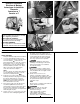
1. Locate the black plastic protective covers
on each side of the vehicle, under the vehicle
next to the bumper
d
. Remove the two
plastic trim fasteners on each side, securing
the protective covers, to access vehicle’s
wiring harness. Locate the vehicle’s wiring
harness behind the protective cover. There
will be connection points matching the
ends of the T-Connector adapter.
NOTE
On some vehicles, the vehicle wiring harness
is located behind the protective cover and
above the rear bumper bracket
ef
.
2. Beginning on the driver’s side, remove the
foam tape attached to the plugs and separate
the vehicle’s wiring harness connectors,
being careful not to break the locking tabs
gh
. Ensure that the mating surfaces are
free of dirt. Clean if necessary.
3. On the driver's side, insert the T-Connector
end, with the
yellow wire, between the
vehicle wiring connectors and lock into place.
Be careful not to damage the locking tabs
and be sure that connectors are fully inserted
with locking tabs in place.
4. Repeat steps 2 & 3 on passenger's side with
T-Connector end containing the
green wire.
READ THIS FIRST:
Read and follow all instructions carefully
before beginning installation.
LISEZ CECI EN PREMIER:
Lire et suivre toutes les instructions
attenrivement avant le montage.
LEA ESTO PRIMERO:
Lea y siga todas las instrucciones cuida-
dosamente antes de iniciar la instalación.
•
d
•
g
•
e
•
f
•
h