
User guide

6. Locate a suitable grounding point near the
connector such as the vehicle's frame or cross
member
k
. (Do not drill into vehicle floor or
bed.) Clean dirt and rustproofing from area.
Drill a 3/32" hole and secure
white wire using
eyelet and screw provided.
CAUTION
Verify what is behind any surface prior to
drilling to avoid damage to the vehicle and/
or personal injury. Do not drill into any
exposed surfaces.
WARNING
All connections must be complete for the
T-Connector to function properly. Test and
verify installation with a test light or trailer
once installed.
7. Mount the T-connector black box using
double-sided tape provided
k
. Secure the
remainder of the T-connector harness with
the cable ties provided. To prevent damage
or rattling, be careful to avoid any areas
that would cut or pinch the wire.
8. Reposition the access panels, trays and trunk
floor panels and reattach the threshold.
NOTE
Store 4-Flat in trunk or rear cargo area when
not in use.
WARNING
Overloading circuit can cause fires. DO NOT
exceed lower of towing manufacturer rating or:
• Max. stop/turn light: 1 per side (2.1 amps)
• Max. tail lights: (5.0 amps)
Read vehicle's owners manual & instruction
sheet for additional information.
ENGLISH
TOOLS NEEDED
10mm Socket & Ratchet or 10 mm Wrench,
Drill, Phillips Head Screwdriver, Test Probe
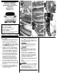
1. Open the vehicle’s rear tailgate. On the
driver’s side remove access panel to locate
rear of taillight
d
. Repeat on the passenger
side. Remove threshold, trunk floor panels and
trays
e fgh
. Set aside all items removed
being careful not to damage parts.
2. Remove two screws in the threshold plate
area
i
, to gain access behind trim panels.
Being careful not to damage clips, partially
remove the lower interior trim panels on each
side of the vehicle
j
. Set aside all items
removed being careful not to damage parts.
3. On the driver and passenger sides of the
vehicle, locate the vehicle's taillight wiring
harness
k
. The taillight wiring harness will
have a connection point, on both sides,
matching the ends of the T-Connector.
Separate these connectors, being careful
not to break the locking tabs. All connector
surfaces should be clean and free of dirt .
4. On the driver’s side insert the T-Connector
end, with the
yellow wire, between the vehicle
wiring connectors and lock into place. Be sure
that connectors are fully inserted with locking
tabs in place.
5. Route the T-Connector end with green wire
to the passenger's side. Repeat step 4 on
the passenger's side with T-connector end
containing the
green wire.
118415-037 Rev. A 06/27/06
Installation Instructions
Directives de Montage
Instrucciones de Instalación
T-Connector
Connecteur en T
Conector en T
READ THIS FIRST:
Read and follow all instructions carefully
before beginning installation.
LISEZ CECI EN PREMIER:
Lire et suivre toutes les instructions
attenrivement avant le montage.
LEA ESTO PRIMERO:
Lea y siga todas las instrucciones cuidadosa-
mente antes de iniciar la instalación.
•
f
•
i
•
e
•
g
•
j
•
h
•
d
•
k