
User Manual

Installation Instructions
Ford Explorer
For vehicles with OEM Tow Hook:
Tow hook must be permanently
removed for hitch installation.
Part Numbers:
75710
87720
44659
78195
U-Haul
Do Not Exceed Lower of Towing Vehicle
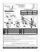
Fascia
Hitch Shown In Proper Position
Equipment Required: Pullwire ( provided),
Lubricant or Soapy water
Wrenches: 18mm, 19mm, 3/4”, 11/16”
and 6” Ratchet extension,
Fastener Kit: 75710F
Do
Not
Exceed
Lower
of
Towing
Vehicle
Manufacturer’s Rating or
Hitch type
Max Gross
Trailer WT (LB)
Max Tongue
WT (LB)
Weight Distributing
5000 (2270 Kg) 500 (227 Kg)
Weight Carrying
Ball Mount
4000 (1816 Kg) 400 (182 Kg)
Wiring Access Location: SUV3 & SUV4
Rubber
isolator
Existing weldnuts
Both sides
3
4
6
6
Figure 2
Reverse pull wire procedure
A. Insert bolt and
block into frame
B. Align block on
access hole
C. Pull bolt thru
block
Hitch exhaust
hangers (2)
1
Qty. (4) Hex bolt M12 x 1.75 x 40mm CL8.8
6
Qty. (2) Bolt carriage 7/16-14 x 2.500 GR5
1
2
1
2
2
5
6
6
78
STEP 3
Must be install before hitch is
raised into position
Figure 1
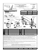
Figure 3
Both sides
6
For vehicles with OEM Tow Hook: Tow hook must be permanently removed for hitch installation.
1.Lower exhaust system at the rubber isolator (3 places). Note: Spraying a lubricant or soapy water on the metal hanger rod and the rubber isolator helps
lR bb ilt f ffl l(2)tb
itllt 3
B f l t t ll ffl t f ll d it i ht
2
Qty. (5) Conical washer 1/2”
7
Qty. (2) Flat washer 7/16
3
Qty. (1) Bolt Carriage ½-13 x 1.50 GR5
8
Qty. (2) Hex lock nut 7/16-14
4
Qty. (1) Spacer ¼” x 1.00 x 2.00
9
Qty. (1) Pullwire
5
Qty. (1) Hex nut 1/2-13
remova
l
.
R
emove ru
bb
er
i
so
l
a
t
or
f
rom mu
ffl
ers on
l
y
(2)
t
o
b
e re‐
i
ns
t
a
ll
s
t
ep
3
.
B
e care
f
u
l
no
t
t
o a
ll
ow mu
ffl
er
t
o
f
a
ll
un
d
er
it
s own we
i
g
ht
.
2.Remove and return exhaust hanger, and/or exhaust hanger with factory tow hook, and fasteners to vehicle owner.
3.Install carriage bolts (item 6) into exhaust hangers on hitch. Install rubber isolators removed in step 1, onto 7/16 carriage bolts on hitch. Install flat
washer, and 7/16‐14 hex lock nut. See Figure 3.
4.Feed ½‐13 carriage bolt and spacer into passenger side frame rail as shown using reverse pullwire procedure. Leave pullwire attached. See Figure 2.
5.Feed pull wire though hole in bracket on passenger side. Raise hitch into position, over exhaust and align with existing weldnuts in frame rail and ½‐13
carriage bolt installed in Step 4. Install M12 hex bolts and conical washer as shown.
6.Remove pullwire and install conical washer and hex nut on carriage bolt.
7.Tighten all fasteners to the required torque specificaion.
8
Raise exhaust back into position (3 places) Note: Spraying a lubricant or soapy water on the metal hanger rod and the rubb
er
isolator helps
8
.
Raise
exhaust
back
into
position
(3
places)
.
Note:
Spraying
a
lubricant
or
soapy
water
on
the
metal
hanger
rod
and
the
rubb
er
isolator
helps
.
Tighten all M12 CL.8.8 fasteners with torque wrench to 68 Lb.-Ft (92 N*M)
Tighten all ½-13 GR5 fasteners with torque wrench to75 Lb.-Ft. (102 N*M)
z 2010, 2011 Cequent Performance Products
Sheet 1 of 3 75710N 6-8-11 Rev. D
Note: check hitch frequently, making sure all fasteners and ball are properly tightened. If hitch is removed, plug all holes in trunk pan or other body panels to prevent entry of
water and exhaust fumes. A hitch or ball which has been damaged should be removed and replaced. Observe safety precautions when working beneath a vehicle and wear eye
protection. Do not cut access or attachment holes with a torch.
This product complies with safety specifications and requirements for connecting devices and towing systems of the state of New York, V.E.S.C. Regulation V-5 and SAE J684.
Form: F205 Rev A 5
-
6
-
05