960 VACUUM TUBE COMPRESSOR OPERATORS MANUAL CONTENTS SAFETY CONSIDERATIONS page 1 INTRODUCTION page 2 APPLICATIONS page 2 INSTALLATION page 3 CONTROL DESCRIPTIONS: " Compressor " Microphone Pre-amplifier " Auxiliary Input page page page page QUICK SET-UP page 8 IF A FAULT DEVELOPS page 9 CONTACTING DRAWMER page 9 TECHNICAL SPECIFICATION page 10 BLOCK DIAGRAM page 11 i 5 5 7 7
COPYRIGHT This manual is copyrighted © 1993 by Drawmer Electronics, Ltd. With all rights reserved. Under copyright laws, this manual may not be duplicated in whole or in part without the written consent of Drawmer. ONE YEAR LIMITED WARRANTY Drawmer Electronics Ltd., warrants the Drawmer 1960 audio processor to conform substantially to the specifications of this manual for a period of one year from the original date of purchase when used in accordance with the specifications detailed in this manual.
1960 OPERATORS’ MANUAL 1 DRAWMER 1960 Dual Vacuum Tube Compressor SAFETY CONSIDERATIONS CAUTION - MAINS FUSE TO REDUCE THE RISK OF FIRE REPLACE THE MAINS FUSE ONLY WITH A FUSE THAT CONFORMS TO IEC 127-2. 250 VOLT WORKING, TIME DELAY TYPE WITH A BODY SIZE OF 20mm x 5mm. THE MAINS INPUT FUSE MUST BE RATED AT 250mA WHERE THE MAINS INPUT VOLTAGE SWITCH IS SET TO 230 VOLTS AC. AND 500mA WHERE THE MAINS INPUT VOLTAGE IS 115 VOLTS AC. THE REAR PANEL H.T.
2 1960 OPERATORS’ MANUAL INTRODUCTION The 1960 is a hybrid vacuum tube/semi-conductor, dual-channel compressor which has numerous applications in studio recording, live sound, location recording, postproduction and as part of a musician's rack system. The microphone input stages feature extremely low noise, balanced input circuitry with additional tube amplification, enabling modern microphones to take on the characteristics of older tube models.
1960 OPERATORS’ MANUAL 3 INSTALLATION The 1960 is designed for standard 19" rack mounting and occupies 2U of rack space. Avoid mounting the unit directly above power amplifiers or power supplies that radiate significant amounts of heat and always connect the mains earth to the unit. Fibre or plastic washers may be used to prevent the front panel becoming marked by the mounting bolts.
4 1960 OPERATORS’ MANUAL POWER CONNECTION The unit will have been supplied with a power cable suitable for domestic power outlets in your country. For your own safety it is important that you use this cable. The unit should always be connected to the mains supply earth using this cable. If for some reason the unit is to be used at a mains input operating voltage which is different to that as supplied, the following procedure must be carried out.
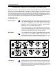
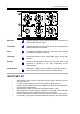
1960 OPERATORS’ MANUAL 5 CONTROL DESCRIPTION AND OPERATION With the exception of the Aux preamp section, both channels of the 1960 are identical and may be used independently or linked for stereo operation. In linked mode, the compressor controls should, ideally, be set to the same settings (as the control-circuitry for both channels responds to the average between the two channel settings).
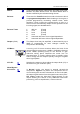
6 1960 OPERATORS’ MANUAL Attack: Three switchable Attack settings are provided giving Fast, Medium and Slow attack times. The actual attack time is further modified by the release setting chosen. Release: There are four fixed Release times and a further two which are programme dependent.
1960 OPERATORS’ MANUAL Stereo Link: 7 Averages the left and right channel control settings when the unit is used for processing a stereo signal. The same degree of gain reduction is applied to both audio channels to prevent image shifting which would otherwise occur whenever the left and right signal dynamics varied from each other by any significant degree. MICROPHONE PRE-AMPLIFIER Mic Input Gain: This fully variable control sets the mic input gain over the range 0 to 60dB.
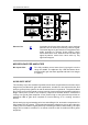
8 1960 OPERATORS’ MANUAL Bass EQ: Passive equaliser control, which can be set to provide up to 15dB of bass boost at 40Hz. Treble EQ: Passive equaliser control, which can be set to provide up to 18dB of treble boost at 16kHz. Gain: Provides up to 30dB of gain at the Low Gain switch setting or 40dB at the High Gain setting. Low/High: Sensitivity selector switch. Adds 10dB of gain in the High position.
1960 OPERATORS’ MANUAL 9 IF A FAULT DEVELOPS For warranty service please call Drawmer Electronics Ltd. Or their nearest authorised service facility, giving full details of the difficulty. On receipt of this information, service or shipping instructions will be forwarded to you. No equipment should be returned under the warranty without prior consent from Drawmer or their authorised representative. For service claims under the warranty agreement a service Returns Authorisation (RA) number will be given.
10 1960 OPERATORS’ MANUAL TECHNICAL SPECIFICATIONS (All measurements taken at +4dBu operating level) INPUT IMPEDANCES LINE MIC AUX 20KÙ 150Ù to 600Ù 2M2Ù -128.
1960 OPERATORS’ MANUAL BLOCK DIAGRAM 11