
Owner manual


DA6 OPERATORS’ MANUAL
MONITOR HEADPHONES
For the purposes of monitorin
g
each output, a stereo ¼" (TRS) jack socket is offered on
the front panel. This havin
g
the standard wirin
g
convention of Tip bein
g
Left; Rin
g
bein
g
Ri
g
ht; and Sleeve bein
g
common Ground. This output is capable of drivin
g
headphones
with an impedance between 8 and 600. The amplifier has an output of approximatel
y
1Watt. Caution is required when operatin
g
at hi
g
h output levels with low impedance
headphones.
DRAWMER do NOT accept an
y
responsibilit
y
for dama
g
e caused to
operator hearin
g
or speaker devices b
y
use of excessive output levels.
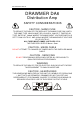
POWER CONNECTION
The DA6 unit will be supplied with a power cable suitable for domestic power outlets in
y
our countr
y
. For
y
our own safet
y
, it is important that
y
ou use this cable to connect to
the mains suppl
y
earth. The cable must not be tampered with or modified.
The power suppl
y
socket has an inte
g
ral fuse drawer containin
g
the power fuse (and a
spare) both of the same value, to suit the mains volta
g
e for which the unit has been
supplied. Removal of the drawer is onl
y
possible with the power cord removed. The fuse
should never blow under normal operation. If the fuse is suspected of havin
g
blown,
then a fault will have occurred and this fault condition should be inspected b
y
a qualified
service en
g
ineer. When replacin
g
the fuse, alwa
y
s compl
y
with the Safet
y
Instructions.
If the unit is to be used with a mains input operatin
g
volta
g
e different to that for which
the unit is supplied, the followin
g
procedure must be carried out b
y
a technicall
y
competent person,
(see followin
g
dia
g
rams)
1: Disconnect the unit from the mains.
2: Usin
g
a number 1 size pozidrive screwdriver, remove the seven self
-tappin
g
screws that retain the top cover. Two screws are found alon
g
each side; two alon
g
the top ed
g
e at the rear; and the upper central screw
on the front facia panel.
3: Slide the volta
g
e chan
g
e-over switch (SW8) until the correct (or nearest)
mains input volta
g
e is visible on the switch actuator.