
Owner manual
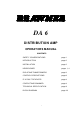


DA6 OPERATORS’ MANUAL
CONTROL DESCRIPTION
The DA6 has been desi
g
ned for ease of use. It operates on balanced or unbalanced
si
g
nal levels in the ran
g
e -15dB to +15dB.(ref. +4dBm)
Input L&R Used to set the optimal input
g
ain for both Left and Ri
g
ht si
g
nals.
Use the displa
y
above to ensure the correct operatin
g
levels are
bein
g
attained. Adjustment in the ran
g
e ±15dB is possible.
Separate controls are offered to permit the re-ali
g
nment of an
y
offset stereo ima
g
e.
These controls also adjust the output level of the auxiliar
y
‘link’
jacks, which implies that an
y
connected slave DA6 will onl
y
require
to have its input trims set to 0dB (verticall
y
).
Input Displa
y
Since the DA6 is normall
y
used as a line amplifier, then it is quite
acceptable to ‘see’ si
g
nals in the positive
g
ain re
g
ion of this
displa
y
. However, ensure that the +15dB LED never illuminates
other than for brief instances, otherwise distortion will occur.
Output L&R These controls should be used to set the optimal output level to
match the input section of the connected device, for both Left and
Ri
g
ht si
g
nals. Adjustment of ±15dB is possible. Normall
y
, an
y
stereo ima
g
e offset will have been corrected b
y
the Left/Ri
g
ht input
controls. However separate output controls are also offered to
g
ive
total control of the stereo ima
g
e.
Mono/Stereo Selects whether the channel output is to be separate Stereo
si
g
nals or ‘summed’ to produce a Mono si
g
nal. If onl
y
one input is
used, this will be output to both sockets if Mono is selected.
Caution should be used when operatin
g
the DA6 with two similar
stereo si
g
nals that are out-of-phase with each other. Under such
conditions, usin
g
the Mono mode will produce ver
y
little usable
output. LEDs show the status of the switch.