
Owner's manual


4
The DMS-3 is designed for standard 19" rack mounting occupying 1U of rack space. Avoid mounting the unit directly above power
supplies or amplifiers that radiate significant amounts of heat. If the unit is to be used in a mobile situation, it is strongly
recommended that the rear of the unit is supported in the carrying rack to avoid bending the front panel rack mounting ‘ears’. Use
fibre or plastic washers to prevent the front panel becoming marked by the mounting bolts.
INSTALLATION
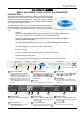
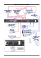
AUDIO CONNECTIONS
Analogue Inputs
The preffered inputs to the A2D2 are electronically balanced
and would normally be connected to your system via a
patchbay. Should unbalanced operation be required, simply
ground pin 3 on the XLR connectors.
If earth loop hum problems are encountered, do not disconnect
the mains earth but instead, try disconnecting one end of the
signal screen on the cables connecting the A2D2 to the
patchbay. If such measures are necessary, balanced operation
is recommended.
AES Input
Via an XLR connector designed to be used with standard
balanced microphone cable (20 metres maximum), wired pin
1 screen, pin 2 and 3 balanced data, and the XLR shell
connected to the chassis. Having many short cables joined
together is not advisable as each connector can cause
undesirable signal reflections.
The output socket fully conforms to the EMC standards; if the
unit is to be used where it may be exposed to high levels of
disturbance, such as found close to a TV or radio transmitter,
it is suggested that the screen of the data cable be connected
to the chassis connection on the XLR type connector rather
than to pin 1.
If ground loop problems are encountered, never disconnect
the mains ground, but instead, try disconnecting the signal
screen on one end of each cable connecting the outputs.
S/PDIF Input
Via a high quality RCA type phono jack where the data conforms
to the SonyJ PhillipsJ Digital InterFace format. Because
this connector only provides an unbalanced termination, the
recommended maximum length for this cable is 3 metres,
even with very high quality cable.
TOSLINK (or EIAJ)
The real benefit of TOSlink is that it is not susceptible to
electromagnetic noise, however, it is highly recommended
that a very good quality cable is used as the plastic conductors
used in cheap cables can damage data. Additionally
performance is compromised over long lengths of cable, as
the signal strength weakens due to impurities in the conductive
material, therefore lengths of no longer than five metres are
recommended unless using a signal booster..
Though the connectors are the same TOSLink and ADAT
Optical are not compatible with each other.
Word Clock
Use only good quality digital or video coax (not aerial
downlead) cable for the word-clock signals, terminated with
the correct type of 75Ω BNC connectors - inferior cables will
introduce jitter and will completely undermine the
performance benefits which might be achieved by using a
master clock in the first place!
The A2D2 will be supplied with a power cable suitable for domestic power outlets in your country. For your own safety, it is
important that you use this cable to connect to the mains supply earth. The cable must not be tampered with or modified.
The power supply socket has an integral fuse drawer containing
the power fuse of the same value, to suit the mains voltage for
which the unit has been supplied. Removal of the drawer is only
possible with the power cord removed. The fuse should never
blow under normal operation. If the fuse is suspected of having
blown, then a fault will have occurred and this fault condition should
be inspected by a qualified service engineer. When replacing the
fuse, always comply with the Safety Instructions.
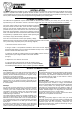
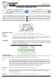
If the unit is to be used with a mains input operating voltage
different to that for which the unit is supplied, the following procedure must be carried
out by a technically competent person, (see following diagram)
1: Disconnect the unit from the mains.
2: Using a number 1 size pozidrive screwdriver, remove the nine self -tapping
screws that retain the top cover. Five screws are located on the top cover; and two
screws on either side. Slide off the cover.
3: Inside the unit slide the voltage change-over switch (VS1) until the correct (or
nearest) mains input voltage is visible on the switch actuator.
(see fig.4)
4: Replace the cover and the nine screws.
5: In the fuse draw change the fuse to suit the following values:
For 230 Volt operation alter the fuse to a similar type rated at T80mA.
For 115 Volt operation alter the fuse to a similar type rated at T160mA.
POWER CONNECTION
FUSE
VS SWITCH