M500 OPERATORS MANUAL
CONTENTS CHAPTER 1 - GETTING STARTED INTRODUCTION HOW TO USE THIS MANUAL INSTALLATION PRECAUTIONS ........................... 1 - 1 ...................................... 1 - 2 ........................... 1 - 2 CHAPTER 2 - THE M500 UNIT FINDING YOUR WAY AROUND IMPORTANT GLOBAL INFORMATION COMBINING EFFECTS PATCH MEMORIES EFFECT EDITING CHAPTER 3 - CONTROL KEY OVERVIEW Bypass Output Meters Thresh Misc Edit / Recall Yes / Accept Assign / Order Midi Links Filter Patch Record Chan 1 / 2 .....................
M500 OPERATORS MANUAL Ch 1 - 1 DRAWMER M500 Dynamics Processor CHAPTER 1 INTRODUCTION The Drawmer M500 has been designed to handle both single or multiple dynamic control operations either in stereo or mono. A single Voltage Controlled Amplifier (VCA) is used in each channel to eliminate the signal degradation that inevitably occurs when several VCA devices are cascaded. The control interface has been designed so that, from the user's point of view, the processes are largely separate.
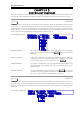
Ch 1 - 2 M500 OPERATORS MANUAL HOW TO USE THIS MANUAL The descriptions in the later sections of this manual make reference to the text that appears on the Liquid Crystal Display (LCD). All possible permutations of text is printed, actual text shown will depend on one or more parameter settings. The possible options printed here will be inside a 'drop-down' menu.
M500 OPERATORS MANUAL Ch 2 - 1 CHAPTER 2 FINDING YOUR WAY AROUND Despite its high degree of sophistication, the M500 has been provided with a friendly and intuitive operating system which issues on-screen prompts where appropriate. Because there are so many parameters attributed to the different Effects, these have been arranged so that the most often used ones are always accessed first allowing the more complex functions to be ignored unless required.
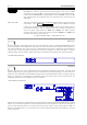
Ch 2 - 2 M500 OPERATORS MANUAL COMBINING EFFECTS The operating system has been designed to allow the two channels of the M500 to be used either independently, or, as linked, stereo pairs. The Effects may be assigned for use in any order with the proviso that the chosen order is logical. As Effects are selected, any remaining, unassigned Effects that it would be illogical to add are removed from the choice and their LEDs extinguished.
M500 OPERATORS MANUAL Ch 3 - 1 CHAPTER 3 CONTROL KEY OVERVIEW Many of the keys are self-explanatory, but because the M500 contains many enhanced features, you should read through this section at least once before getting down to any serious work. BYPASS Primary function: Override all or one dynamics process(es). Because the M500 is really several units in one, it would not be appropriate to have a single bypass switch which could only switch all the Effects in or out of the signal path.
Ch 3 - 2 dc MIDI VOLUME M500 OPERATORS MANUAL This is the facility to add make-up gain to the COMPRESSOR and DE-ESSER to restore level lost during processing. This can be made automatic by selecting Au or can be set manually to a specified amount. If either the COMPRESSOR or DE-ESSER is set to its AUTO mode, then Au will automatically be selected and the optimised gain setting will be displayed.
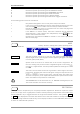
M500 OPERATORS MANUAL Ch 3 - 3 Character Character Character Character Character Character ˆC Ĉ D̂ ˆ D ˆÊ E Ĝ ˆ G ˆL̂L ˆP̂ P symbol symbol symbol symbol symbol symbol representing representing representing representing representing representing the the the the the the COMPRESSOR threshold. DE-ESSER threshold. EXPANDER threshold. GATE threshold. LIMIT threshold. PAN audio trigger threshold. The following points must be considered: • • Only Effects assigned to the current patch may be accessed.
Ch 3 - 4 M500 OPERATORS MANUAL YES ACCEPT The only function of this key is in response to screen prompts to confirm or store changes. ASSIGN Primary function: Confirm and alter the order of dynamic processes. To set up a patch of one or more Effects, the desired Effects have to be 'assigned' before they can be used. An assignment is simply a selection of Effects that may be used together and also, if required, may be stored as a user patch for later use.
M500 OPERATORS MANUAL Ch 3 - 5 • When an incorrect selection is made, it is possible to re-start by hitting ASSIGN followed by YES Once a satisfactory order has been constructed, a prompt to hit ASSIGN again completes the procedure. • If the M500 is not set in Stereo mode, then this procedure must be repeated for the other channel where a different Effect assignment may be set up if so desired. See also LINKS MIDI Primary function: Controls MIDI operation and functions.
Ch 3 - 6 M500 OPERATORS MANUAL FIRST MIDI PARAMETER DISPLAY MIDI CHAN Low-SPLIT-Hig A receive and transmit MIDI channel can be set differently for both audio channels, ranging from 1 to 16 16. Other options can be OMN I or OFF OFF. In OMNI mode, the M500 will respond to data received on any MIDI channel but will always transmit MIDI data on channel 1.
M500 OPERATORS MANUAL Ch 3 - 7 SECOND MIDI PARAMETER DISPLAY TRIG TIME TRIG MODE FADE SWITCH MIDI START/STOP SWITCH NUMBER DOWN The TRIGger TIME relates to the way in which the unit responds to incoming MIDI clock in either the triggered GATE or PAN modes. The adjustment range goes up to a maximum of 9 beats and 2 3 frames where frames represent individual MIDI Clock pulses. In a song running 4/4 time, this is one frame less than 2 whole bars and 2 beats.
Ch 3 - 8 M500 OPERATORS MANUAL THIRD MIDI PARAMETER DISPLAY PATCH CHANGES MASTER VOLUME DOWN When set to YES YES, allows the M500's 128 patches to be remotely selected and loaded ready for use over MIDI using standard MIDI program change messages. When the NO option is selected, the M500 will not respond to incoming program changes, but all other relevant MIDI information will still be accepted.
M500 OPERATORS MANUAL Ch 3 - 9 which may be in the range 1 to 127 127, OMNI or OFF OFF. Selecting OFF makes the unit ignore any Sysex data received and disables the Transmit function though other MIDI data is handled as usual. In order to dump data to either another M500 or to a MIDI sequencer, the send and receive device numbers must be set the same, or the receive device set to ChOmni in which case the send channel is irrelevant.
Ch 3 - 10 M500 OPERATORS MANUAL THE LINKS DISPLAY GATE EXP FADE Ds/Cp/Lm NO PAN LINK GATE link has three possible options. On will copy the current channel's parameters to the other channel. Any further GATE parameter adjustments will be duplicated on the other channel. Off reverts to normal single channel operation. GATE link also has a TRI G option.
M500 OPERATORS MANUAL STEREO GLOBAL Ch 3 - 11 Other relevant parameters are also linked such as OUTPUT GAIN, COMPRESSOR DC MAKEUP and the function of the BYPASS button. This ensures that the user has not accidentally overlooked any parameters that might otherwise cause the channels to behave differently. However, the user must ensure that the OUTs parameter is set to 1<>2 to allow dual-channel output operation.
Ch 3 - 12 M500 OPERATORS MANUAL To avoid possible confusion as regards the LINK settings, especially in the cases of the more advanced Effects, it is recommended that the user experiment with a preset patch which includes the desired linked Effect and make tiny adjustments, rather than attempting 'Linked Effects' from scratch. FILTER Primary function: Side chain filter for GATE and DE-ESSER.
M500 OPERATORS MANUAL DOWN Ch 3 - 13 Makes a change only in signal monitoring The lefthand word Filtr in lower case. Functions in exactly the same way as above but the monitor signal is now the output of the GATE or DE-ESSER to which the filter has been assigned, and not the actual signal passing through the filter. Filtr Assigning the filter to the DE-ESSER takes priority over the GATE as the DE-ESSER is not able to function in any mode without use of the filter, where as the GATE can.
Ch 3 - 14 M500 OPERATORS MANUAL THE PATCH DISPLAY FOR SAVE SAVE PATCH(es) YES will save the current patch from the current channel. The SAVE Patch option will automatically detect which LINK mode (eg. Stereo) is in operation and will offer various suitable save methods. If dissimilar stereo patches are being saved, the following display will be seen. SECONDARY PATCH DISPLAY FOR A STEREO SAVE DOWN MIDI CHANGES The last (bottom) screen encompasses MIDI CHANGES and MEMORY PROTECTION.
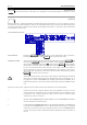
M500 OPERATORS MANUAL Ch 3 - 15 • The white graduation above the display window can be used to maximise the input envelope amplitude. • When the envelope is later used with the GATE Effect, for it to respond as a true noise gate envelope the following should apply: The input level during record should reach 0dB at least once. Any input level above 0dB will react similar to GATE PEAK. The final input level of the envelope must be as close to -90dB as possible for the GATE to fully close.
Ch 3 - 16 M500 OPERATORS MANUAL FINISHED RECORD DISPLAY ENVELOPE NUMBER Once recording is complete, the envelope number is displayed and may be changed, ranging from 1 to 16 16. If a previously recorded number is selected, this will be overwritten. RECORD NAME The envelope may be given a title of up to ten characters. If a previously recorded envelope is selected, this will be overwritten.
M500 OPERATORS MANUAL Ch 4 - 1 CHAPTER 4 BASIC EFFECT OPERATION The Effects are accessed via the seven yellow keys on the bottom row of the keypad, and an Effect may be selected for experiment by hitting ASSIGN then YES and then your choice of Effect. Confirm your selection. Then hit the Effect key again to access the parameters on the appropriate screen display.
Ch 4 - 2 M500 OPERATORS MANUAL setting in dBs. In other applications such as separating dialogue from background noise, it is often more natural to merely attenuate the background noise rather than attempt to remove it completely. Side-chain filtering is available though the access to this is via a page further down the menu. The filter is set up using the FILTER key on the front panel and it is used exactly like the filter on a DS201 GATE.
M500 OPERATORS MANUAL Ch 4 - 3 BASIC LIMIT LIMITERs are used to impose more firm control over signal dynamics than a COMPRESSOR and are often used to set an absolute maximum level that the signal being processed must not exceed. Technically, the function of a LIMITER is identical to that of a COMPRESSOR but the ratio is higher. This Effect has the same user-adjustable parameters as the COMPRESSOR. There is a choice of manual or auto (programme dependent) release time.
Ch 4 - 4 M500 OPERATORS MANUAL BASIC FADER In the FADER mode, the M500 can be used to fade in or out either a stereo signal or two mono signals. In the mono mode, the two channels can be given different fade in and out times though the same trigger source is automatically selected for both channels. There are three possible trigger modes which may be selected from the FADER menu: View, MIDI and Timer.
M500 OPERATORS MANUAL Ch 4 - 5 It is necessary to set up the filter via the FILTER key and menu so that only the most sibilant sounds are passed. This is best done by monitoring the filter output while the offending signal is present and then tuning the filter so that it captures as much as possible of the sibilant sound and as little as possible of the rest of the material. Back on the DE-ESS page, the parameters can be set up in a similar way to setting up the COMPRESSOR.
M500 OPERATORS MANUAL Ch 5 - 1 CHAPTER 5 ADVANCED EFFECT OPERATION The Effect modules described fully in this chapter are listed as they appear on the M500 front panel, working left-to-right. The format for each effect is similar describing each parameter's function and capabilities. The descriptions end with a list of suitable factory patches, which can be loaded and tried with the suggested material or programme.
Ch 5 - 2 M500 OPERATORS MANUAL 1<-- Two band Comp Not just a De-Esser, but offering two programmable frequency dependant compressors. Both filters are used to determine the side chain response and the band being compressed. Again, this mode may only be used by channel 1 input and the output will normally appear at channel 1 output. It is however possible to unlink the two bands so that each appears at a separate output if the need arises.
M500 OPERATORS MANUAL Ch 5 - 3 This determines how much Gain Reduction occurs when the input signal goes above THRESHold. The parameter range covers from 1.1:1 to 20:1 20:1, with TYPE set to Norm Norm, or, from Sft:0 to Sft:9 with TYPE set to Soft Knee. The amount of Gain reduction, or Compression, depends upon the THRESHold, RATIO and TYPE settings and the input signal level. eg.
Ch 5 - 4 M500 OPERATORS MANUAL DE-ESS EXAMPLES To do simple vocal DE-ESSing, select the desired channel to be DE-ESSed, load the patch number 83 called De S Vocal Vocal. Hit THRESH and reduce the sibilance to the required level by rotating the knob anti-clockwise. Adjust the De-essing frequency hit FILTER and select the lowest (bottom) screen page, adjust the filter to display the audio band that you wish to compress.
M500 OPERATORS MANUAL Ch 5 - 5 ATTACK is the rate at which the GATE opens from the RANGE setting. Too fast an attack coupled with too high a threshold will cause 'clicks' (square edges) onto low-frequency programme material. The fastest attack setting is 3µS 3µS, the slowest being 10S 10Seconds ATACK HOLD is the time GATE remains open, after any Peak Envelope has finished. The minimum HOLD time is 8mS and the maximum is 20S 20Seconds.
Ch 5 - 6 M500 OPERATORS MANUAL Screen 3 introduces a new parameter, Peak Level, which may be used to actually increase the level of the processed sound for a short time immediately after the Gate has opened. This has its own Level, Peak Time and Decay times which allow transients such as drums to be given extra attack. Once the decay time has elapsed, the Gate completes its envelope conventionally. This screen of parameters will not be available if RECORDED envelope TYPE is selected.
M500 OPERATORS MANUAL Ch 5 - 7 GATE TRIGGER PARAMETERS FOR BOTH TYPES TRIGGER Selects the source information that will trigger the gate. There are four possible options. The standard choice will be Audio Audio, but sophisticated MIDI options are also offered: MIDIbeat - where MIDI time information will fire the GATE. The time information can be divided down using the MIDI parameter.
Ch 5 - 8 M500 OPERATORS MANUAL BReTrig Where the Gate envelope is forced to finish regardless of the envelope of the triggering sound and will then trigger on the next sound after the retrigger time has elapsed. Type B will cause repeating envelopes on a continuous valid trigger, whereas type A would remain open. ReTRIG-LEVEL The is a secondary threshold that the audio signal has to fall below to permit the GATE to close, it is very effective in 'Latching on' to a sound once triggered.
M500 OPERATORS MANUAL Ch 5 - 9 ADVANCED EXPAND The Expander section may be used as a low level or downwards Expander in much the same way as a noise Gate, or it may be used to increase the dynamic range of a signal by setting a higher threshold but selecting a low expansion ratio and applying some Output gain. Aside from the View screen, there is only one screen needed to set up the Expander parameters. The user variable parameters are:- Threshold, Ratio, Attack, Hold, Release and Range.
Ch 5 - 10 RANGE EXPAND PATCHES M500 OPERATORS MANUAL The range parameter can be set so that the EXPAND effect is operational but not too severe. The maximum range of 40dB is only available with higher RATIO and THRESHOLD settings. Patches numbered 66 to 71. Combinations with other Effect modules patches can be found at patch 101 and patch 103 ADVANCED COMPRESS The Compressor is relatively simple to set up and uses only one parameter screen in addition to the View screen.
M500 OPERATORS MANUAL Ch 5 - 11 COMPRESS VIEW METERS DOWN COMPRESS PARAMETERS DISPLAY This sets the signal input level over which Gain Reduction will start to occur. The manual threshold ranges from -30dB to +15dB (a setting of +15dB will cause very little audible change). For details of the Auto setting see above. THRESH This determines how much Gain Reduction occurs when the input signal goes above THRESHold. The parameter range covers from 1.
Ch 5 - 12 TYPE M500 OPERATORS MANUAL Soft This being a Soft Soft-Knee type compressor which is very transparent. In SoftKnee mode however, the compression ratio increases as the signal level increases and so there is no hard and fast threshold as such. In Soft-Knee, the THRESHOLD parameter is used to adjust the amount of compression, and RATIO alters the curve of the knee, making it softer or harder on a scale of 0 to 9. COMPRESS PATCHES Patches numbered 73 through and including 80.
M500 OPERATORS MANUAL Ch 5 - 13 This is the rate at which the Gain Reduction increases once the input signal exceeds THRESHold. This parameter should be kept fairly short if it is desired to prevent any peaks passing through unprocessed. The manual range of this parameter is 20µs (letting no peaks through) to 5.0ms (which allows some peaks to pass through). ATACK Length of time that Gain Reduction holds for when signal causes an increase. Useful for low frequency sounds to prevent 'Rattle'.
Ch 5 - 14 M500 OPERATORS MANUAL Displays the name of the currently selected factory preset PAN waves. Eight waves are offered with 'Sine' being the PAN wave conventionally used. The variety of waveforms include: Sine Duo Sine Tri Sine Triangle Steps Ramp Wide Sqr Square. --WAVE-- Out gives the standard PAN Effect which sweeps from one channel to the other, ie. the amplitude of one channel increases as the other decreases.
M500 OPERATORS MANUAL Trig-SOURCE Ch 5 - 15 MIDInote MIDInote triggering is not actually triggering of the pan envelope at all, but literally MIDI notes set the PAN position with respect to the Low and High key split points currently selected for audio channel 1, (see the MIDI screen).
Ch 5 - 16 M500 OPERATORS MANUAL DOWN FADER PRIMARY PARAMETERS DISPLAY This time is the time per 10dB of gain increase. So a setting of 10ms (the minimum) will take 90ms to rise and 10S 10Seconds (the maximum) will take 90 seconds to rise from a floor of -90dB. Fade UP This time is the time per 10dB of gain decrease. So a setting of 10S 10Seconds will take 90 seconds to fall to a floor of -90dB, although little change might be perceived once the signal has fallen below 60dB or so.
M500 OPERATORS MANUAL Ch 5 - 17 FADER TIMER PARAMETERS DISPLAY OUT--Time Time--ELAPSED Either programmable by the user to a precise time, or previously set with a 'dry-run' of the material to be FADED. It is the time when the FADE down will commence, at the set FADE DOWN rate. The OUT--Time can be set automatically by selecting the timer Minutes value to below 0 . Then, once the audio has exceeded the first hidden threshold the timer will count until YES is hit.
M500 OPERATORS MANUAL Ch 6 - 1 CHAPTER 6 PRESET 'Factory' PATCHES PATCH # TITLE TYPE DESCRIPTION 51 Gate Snare 1Chan Standard Gate using a suitable filter for snare drum. 52 Gate Kick 1Chan Gate with Peak using a suitable filter for kick drum. 53 Gate Tom 1Chan Longer Gate with some re-trigger, using filter for tomtom. 54 Gate Cymbl 1Chan Fast Attack Gate with long envelope and Peak using suitable filter. 55 Gt Rev Cym 1Chan Use with crash cymbal (or noise) for reverse envelope effect.
Ch 6 - 2 M500 OPERATORS MANUAL PATCH # TITLE TYPE DESCRIPTION 77 Comp Soft 78 CmpSloSoft 1Chan Soft knee Comp with long Attack and auto Release. (2) Hidden Auto presets : 50ms attack / 10sec hold / 20sec decay; but not invoked 79 Auto level 2Chan Very long release Comp with auto gain make-up. (2) Hidden Auto presets : 25ms attack / 10sec hold / 30sec decay; but not invoked 80 Comp Ster 2Chan Gentle stereo Compressor for use at mixdown.
M500 OPERATORS MANUAL Ch 6 - 3 PATCH # TITLE TYPE DESCRIPTION 107 Shimmer Stereo Triggered modulation on HF band (Chan 1 only) 108 Shimmer Stereo 109 Piano Pan 2Chan Ch1 input, Stereo output, for electric piano type sounds. 110 Filter Pan Stereo Low frequencies to Ch1 and High frequencies to Ch2 111 Filter Pan Stereo 112 FiltrPhaze Stereo Ch1 output Phasing effect. 113 FiltrPhaze Stereo 114 M C3 Gate 2Chan MIDI Note C3 (only) will trigger Gate, with Peak.
Ch 6 - 4 M500 OPERATORS MANUAL PATCH TYPE Stereo A Patch marked Stereo is a single patch that is loaded into both channels simultaneously. This saves memory storage space when compared to a 2Chan type of patch. Space for 50 User patch of this type is available. All the MIDI patches (numbers 114 to 128) have the MIDI receive channel set to '1'. This might have to be changed to suit your MIDI set-up.
M500 OPERATORS MANUAL Ch 6 - 5 SIDE CHAIN INSERT JACK The side chain insert jack, (called S/C jack), on the rear panel of the M500 has several positions in the control circuit dependent on the Effect assignment. EFFECT MODULE SIDE CHAIN JACK USE None assigned S/C Jack has no use, although input signal is present at the 'send' contact. GATE (direct source) S/C Jack has input signal for GATE detection. Breaking the jack will stop the GATE operating.
M500 OPERATORS MANUAL Ch 7 - 1 CHAPTER 7 M500 MIDI IMPLEMENTATION CHART FUNCTION TRANSMITTED RECOGNISED REMARKS 1 - 16 1 - 16, & Omni 'Off' option disables MIDI Mode Default Messages Altered Mode 3 No No Mode 3 No No Note Number Velocity Note On Velocity Note Off Aftertouch Keys 1 - 127 Yes No No 1 - 127 No No No Channel Pressure No No Pitch Bender No No Control Changes #6 #7 #64 Yes No No Yes Yes Yes #65-95 #70-94 #96,97 No No Yes Yes Yes Yes Program Change 0 - 127 0 - 127 Sys
Ch 7 - 2 M500 OPERATORS MANUAL SYSTEM EXCLUSIVE DATA FORMAT The format of MIDI Exclusive data dumps for M500 is as follows:MIDI DESCRIPTION DATA BYTE HEX EXPLANATION SYSTEM EXCLUSIVE 11110000 0F0 Standard MIDI spec. MANUFACTURERS ID 00110010 032 "Drawmer Electronics" DEVICE NUMBER 0xxxxxxx 0 to 07F FORMAT NUMBER 0000xxxx 0 to 7 MSB DATA COUNT 0000000x 0xxxxxxx 0 or 1 0 to 07F MSB of data size to follow. Sent as two bytes.
M500 OPERATORS MANUAL Ch 7 - 3 EXCLUSIVE FORMAT REQUEST The procedure to remotely request a specific Format of MIDI Exclusive data dump for M500 is as follows:MIDI DESCRIPTION DATA BYTE HEX EXPLANATION SYSTEM EXCLUSIVE 11110000 0F0 Standard MIDI spec. MANUFACTURERS ID 00110010 032 "Drawmer Electronics" DEVICE NUMBER 0xxxxxxx 0 to 07F See MIDI device channel number FORMAT NUMBER 0100xxxx 0 to 7 + 64 See EXCLUSIVE DUMP NUMBERS above END OF EXCLUSIVE 11110111 0F7 Standard MIDI spec.
M500 OPERATORS MANUAL Ch 8 - 1 CHAPTER 8 SAFETY CONSIDERATIONS CAUTION - MAINS FUSE TO REDUCE THE RISK OF FIRE REPLACE THE MAINS FUSE ONLY WITH THE SAME TYPE, WHICH MUST BE A CLASS 3, 240 VOLT, SLO-BLO TYPE, RATED AT 80mA WHERE THE MAINS INPUT VOLTAGE SWITCH IS SET TO 240 VOLTS AC. AND 160mA WHERE THE MAINS INPUT VOLTAGE IS 110 VOLTS AC. THE FUSE BODY SIZE IS 20mm x 5mm. For units with serial numbers 100 to 400. The fuse rating printed on the rear panel was incorrect. Fit a fuse as rated above.
M500 OPERATORS MANUAL Index - 1 INDEX 1<-- explained 1<>2 explained 1Chan explained 2Chan explained Assign Change Order Of display Illogical View Order of ATTACK Advanced COMPRESSOR Advanced DE-ESS Advanced EXPAND Advanced GATE AUTO, Advanced COMPRESSOR Ch 3 - 11 Ch 3 - 11 Ch 6 - 3 Ch 6 - 3 Ch Ch Ch Ch 3 3 3 3 - 4 4 4 4 Ch 5 - 11, Ch 5 - 13 Ch 5 - 3 Ch 5 - 9 Ch 5 - 5 Ch 5 - 10 Basic COMPRESS Ch 4 - 2 Basic EXPAND Ch 4 - 2 Basic GATE Ch 4 - 1 Basic LIMIT Ch 4 - 3 Peak LEVEL advanced GATE Ch 5 - 6 Br
Index - 2 DE-ESS TYPE, Advanced COMPRESSOR O/L LEDS clipping OUTPUT AUTO Gain Make-Up DC Makeup Display MIDI sets Gain PAN Image, start position Re-Trigger envelope PATCH changed by MIDI Load Memory protect Preset type Save User * type User type PHASE Advanced PAN Basic PAN RANGE Advanced EXPAND Advanced FADER Advanced GATE Advanced PAN Basic EXPAND Basic GATE Basic PAN RATE Advanced GATE (RECORDED) Advanced PAN Basic PAN Record RATIO Advanced COMPRESSOR Advanced DE-ESS Advanced EXPAND Basic COMPRESS Basic