DRAWMER CONTENTS Warranty . . . . . . . . . . . . . . . . . . . . . . . . . . . 3 ..................3 Safety Consideration ...........3 Radio Frequencies Statement Chapter 1 - Introduction Introduction . . . . . . . . . . . . . . Installation . . . . . . . . . . . . . . . Power Connection . . . . . . . . . . . Portable Applinace Testing . . . . . Audio Connection . . . . . . . . . . . Typical Connection Guide . . . . . . . . . . . . .. .. .. .. .. .. .... .... .... .... .... .... .. .. .. .. .. .. .
DRAWMER 2
COPYRIGHT This manual is copyrighted © 2013 by Drawmer Electronics Ltd. With all rights reserved. Under copyright laws, no part of this publication may be reproduced, transmitted, stored in a retrieval system or translated into any language in any form by any means, mechanical, optical, electronic, recording, or otherwise, without the written permission of Drawmer Electronics Ltd. ONE YEAR LIMITED WARRANTY Drawmer Electronics Ltd., warrants the Drawmer MC2.
DRAWMER MC2.1 CHAPTER 1 Monitor Controller W ith the Drawmer MC2.1 Monitor Controller incorporated into your system you combine the clarity, fidelity and transparency of the highest quality monitoring circuit with the complexity of a host of mix checking features. It is versatile and intuitive, but above everything else, where the Drawmer MC2.1 excels is in it’s accuracy and ability to faithfully reproduce what has been recorded. The MC2.
Whether you’re mastering a cd/dvd, recording, checking a mix for balance and e.
DRAWMER INSTALLATION The MC2.1 is a free standing, desktop unit, with controls and headphone jacks on the front panel and all other inputs and outputs on the rear. Multiple units can be stacked whilst sitting on the desk, however, the MC2.1 can be screwed to the desk or into a standard 19” rack (using a 2U mounting kit).
POWER CONNECTION The MC2.1 unit will be supplied with a power cable suitable for domestic power outlets in your country. For your own safety, it is important that you use this cable to connect to the mains supply earth. The cable must not be tampered with or modified. The power supply socket has an integral fuse drawer containing the power fuse of the same value, to suit the mains voltage for which the unit has been supplied. Removal of the drawer is only possible with the power cord removed.
DRAWMER AUDIO CONNECTIONS • Interference: If the unit is to be used where it maybe exposed to high levels of disturbance such as found close to a TV or radio transmitter, we advise that the unit is operated in a balanced configuration. The screens of the signal cables should be connected to the chassis connection on the XLR connector as opposed to connecting to pin1. The MC2.1 conforms to the EMC standards.
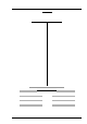
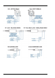
TYPICAL CONNECTION GUIDE MC2.
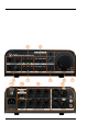
DRAWMER CHAPTER 2 CONTROL DESCRIPTION As well as a transparent and precise signal path the MC2.1 Monitor Controller incorporates many impressive features which are invaluable to the sound engineer when listening to and examining the quality of the audio: Three stereo balanced speaker outputs, plus mono speaker/sub-woofer output. with individual level control for level matching. Comprehensive mix checking facilities. Four simultaneously selectable inputs.
The MC2.1 Controls 1 SOURCE Three switches select which of I/P1, I/P2 and AUX is heard (see 8 ). Each can be operated individually or simultaneously and in any combination. W hen operated simultaneously the individual signals are summed into a single stereo signal. Note that the MC2.1 does not provide individual level trims for the inputs and so any level matching should be applied before it reaches the MC2.1.
DRAWMER Mix Checking cont.... Under the Cut heading three switches have been incorporated - Left Cut, Mute and Right Cut. Left Cut: Mutes the Left channel signal allowing only the right signal to be heard, Right Cut: Mutes the Right channel signal allowing only the left signal to be heard, Mute: Cuts both channels (especially useful in an emergency). If Left Cut and Right Cut are both active it is just the same as Mute being active.
Talkback Level. The knob adjusts the gain level of the talkback microphone. It can be adjusted to compensate for the distance that the operator is from the microphone, how loud his voice is, or the volume of the underlying music played, as well as several other factors. TalkBack Microphone. An electret condenser microphone as been incorporated into the MC2.1 and is located above the Talkback Level on the front panel. Activating the Talkback automatically engages the Dim switch (i.e.
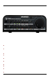
DRAWMER 8 INPUTS The MC2.1 has four inputs comprising a I/P1 - a balanced Neutrik XLR, I/P2 - a balanced Neutrik XLR/jack combi (combining a 3 pole XLR receptacle and ¼" phone jack in one XLR housing), and also AUX. - a shared input comprising of stereo RCA’s and a 3.5mm stereo jack.
11 MAINS I.E.C. AND POWER SWITCH The mains inlet, I.E.C., which also incorporates the internal mains fuse, can be found on the rear of the unit. A mains lead will have been provided with the MC2.1 to suit the mains configuration for the country of your purchase. The power switch is located above the I.E.C. and is used to switch the unit on and off. This is a hard boot switch (as opposed to a soft stand-by switch) and so when in the off position the MC2.1 will draw no mains power.
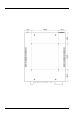
DRAWMER MONITOR CALIBRATION Whether you are installing one, two or three sets of speakers it is imperative that your system is calibrated, not only to centre the stereo image and to ensure that all speaker levels are the same, but also to ensure that you are mixing your music at industry standard listening levels. The MC2.1 can calibrate the speakers of any system as it has individual rotary level trim controls for every speaker attached (found on the under-side of the product).
Holding the SPL - Set the meter to C weighted and on the slow scale. Start by sitting in your normal mixing position, hold the SPL meter at arm’s length and at chest level with the microphone of the meter facing toward the monitor to be calibrated. Maintain this position throughout the calibration process - this could be easier if it is fixed via a stand and bracket, and moved only to point at the relevant speaker.
DRAWMER The Procedure: 1. Begin by turning off the monitoring system and ensuring that all inputs and speakers are correctly connected. 2. Set all DAW/System controls to 0dB/unity gain - this should be left at this setting from now on. Remove all e.q. and dynamics from the signal path. 3. If you have active speakers with their own level control, or speakers with an amplifier, set all of these to maximum, so that they do not attenuate the signal. 4. On the underside of the MC2.
11. On the underside of the MC2.1 rotate the Right A trim clock-wise until the SPL meter reads the desired level. 12. To calibrate each speaker repeat steps 7 to 11 - replacing the speaker on step 7 for each set - A,B or C. 13. To calibrate the sub - play the 40-80Hz signal, but this time have only Speaker A active - Left and Right Cut need not be active as the frequency of the signal is limited to only the sub. 14. On the underside of the MC2.
DRAWMER Mix Checking Tips Due to the versatility of the MC2.1, and it’s thorough array of controls, some very useful techniques for checking your mix can easily be achieved, that can help improve the balance within a mix, pinpoint stereo width, phase and mono problems, and also aid when monogising. The following are a few handy tips to help eradicate problems and bring about a balance within the mix: Not too loud... Give your ears a break.
Cut It Out... Using the left and right cut switches will highlight the stereo balance of each channel. In stereo the mix sounds ok, however, it may be that you want an instrument to be panned so far left that it doesn’t occur at all in the right channel, by cutting the left and only hearing the right channel you will hear whether the instrument bleeds across, and panning adjustment can be made. Phase Reverse... Make use of the phase reverse switch.
DRAWMER Listening in mono also highlights problems with the stereo width and balance of the mix and is more apparent when you use a lot of stereo-widening or widthenhancing techniques and tools. Switching mono in and out fairly quickly may make it apparent that the centre of the mix is shifting to the left or right, something that may go unnoticed if only working in stereo.
CHAPTER 3 MC2.1 GENERAL INFORMATION IF A FAULT DEVELOPS SPECIFICATION For warranty service please call Drawmer Electronics Ltd. or their nearest authorised service facility, giving full details of the difficulty. A list of all main dealers can be found on the Drawmer webpages . On receipt of this information, service or shipping instructions will be forwarded to you. Note: These specfications are provisional and may alter slightly upon product release.
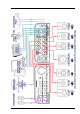
DRAWMER BLOCK DIAGRAM Ref:1v01E 08-04-14 24