DRAWMER Stereo Vacuum Tube Compressor with Instrument & Mic Pre OPERATORS MANUAL CONTENTS SAFETY CONSIDERATIONS INTRODUCTION INSTALLATION • Audio Connections • Power Connection • Digital Module CONTROL DESCRIPTIONS • Analogue • Digital OPERATION IF A FAULT DEVELOPS CONTACTING DRAWMER TECHNICAL SPECIFICATION BLOCK DIAGRAM i page 1 page 2 page 2 page 3 page 4 page page page page page page page 5 8 9 12 12 13 14
COPYRIGHT This manual is copyrighted © 2002 by Drawmer Electronics, Ltd. With all rights reserved. Under copyright laws, this manual may not be duplicated in whole or in part without the written consent of Drawmer. ONE YEAR LIMITED WARRANTY Drawmer Electronics Ltd.
1 Tube Station 1 OPERATORS’ MANUAL DRAWMER Tube Station 1 Stereo Vacuum Tube Compressor with Instrument & Mic Pre SAFETY CONSIDERATIONS CAUTION - MAINS FUSE TO REDUCE THE RISK OF FIRE REPLACE THE MAINS FUSE ONLY WITH THE SAME TYPE, WHICH MUST BE A CLASS 3, 250 VOLT, TIME DELAY TYPE, RATED AT 160mA WHERE THE MAINS INPUT IS SET TO 230 VOLTS AC. AND 315mA WHERE THE MAINS INPUT VOLTAGE IS 115 VOLTS AC. ALL FUSES MUST COMPLY WITH IEC127-2. THE FUSE BODY SIZE IS 20mm x 5mm.
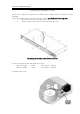
2 Tube Station 1 OPERATORS’ MANUAL INTRODUCTION The Tube Station 1 is a high quality Stereo Vacuum Tube Compressor with Instrument & Mic Pre. It has an optional Digital Output module which enables SPDIF and AES/EBU to be output from the unit. The Tube Station 1 is suitable for both live sound and studio applications. All buttons have status LEDs. INSTALLATION The TS1 is designed for standard 19" rack mounting and occupies 1U of rack space.
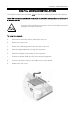
3 Tube Station 1 OPERATORS’ MANUAL POWER CONNECTION If the unit is required to operate at a mains input voltage which is different to that supplied: The following procedure must be carried out by a qualified technical engineer. 1: Disconnect the unit from the mains. 2: Remove the twelve screws that retain the top cover. Accessing the internal power switch and fuse 3. Set the voltage rating and replace the fuse. Mains Voltage 230V Fuse Value Mains Voltage 115V Fuse Value 4. Replace the cover. 160mA.
4 Tube Station 1 OPERATORS’ MANUAL DIGITAL MODULE INSTALLATION The Digital modules are designed only for operation within a Drawmer Tube Station. Under NO circumstances should the module be installed into any other manufacturers’ or custom device. Full anti static handling precautions must be followed to prevent damage to sensitive circuitry. To Install the module: a: Disconnect the mains power cable from the unit. b: Remove the top cover. c: Remove the blanking panel from the rear of the unit.
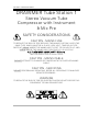
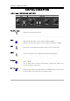
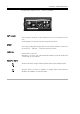
Tube Station 1 OPERATORS’ MANUAL 5 CONTROL DESCRIPTION INPUT and FRONT END SECTION Pre-Amp Input Selects the Instrument input ................................................................................ Gain 48V Adjusts the Mic Gain over a range of 0dB to 60dB. Adjusts the instrument gain over a range of !20dB to +40dB. Switches on the phantom power if Mic source is selected. 2Rev Inverts the phase of the signal leaving the preamplifier. ..........................................................
6 Tube Station 1 OPERATORS’ MANUAL COMPRESSOR SECTION Source Compressor Attack Release Selects between the Line Input and the Front End Section. This serves as the input gain control to the compressor which has a preset threshold. Rotate clockwise until the required amount of compression is achieved. The amount of compression is indicated by a LED bar indicator on the front panel. Attack controls the speed at which the compressor responds to a rise in signal level.
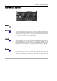
Tube Station 1 OPERATORS’ MANUAL 7 TUBE DRIVE Tube Drive Active A variable control that regulates the amount of tube colouration. Note: even with the control rotated fully counter-clockwise some tube warmth will be added. To disable the tube stage fully, the section must be switched off. Switches the tube circuitry into the signal path and illuminates the status LED.
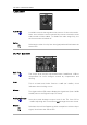
8 Tube Station 1 OPERATORS’ MANUAL DIGITAL OUTPUT - OPTIONAL EXT CLOCK SPDIF AES/EBU Auto detects whether a valid external clock is connected to the unit. A Led lights to indicate that the signal has locked. Via a high quality RCA type phono jack where the data conforms to the Sony™ Phillips™ Digital InterFace format. Via an XLR connector. Wired pin 1 screen, pin 2 and 3 balanced data, and the XLR shell connected to the chassis. SAMPLE RATE Selects between Single Sample Rate and Double Sample Rate.
Tube Station 1 OPERATORS’ MANUAL 9
10 Tube Station 1 OPERATORS’ MANUAL
Tube Station 1 OPERATORS’ MANUAL 11
12 Tube Station 1 OPERATORS’ MANUAL IF A FAULT DEVELOPS For warranty service please call Drawmer Electronics Ltd. Or their nearest authorised service facility, giving full details of the difficulty. On receipt of this information, service or shipping instructions will be forwarded to you. No equipment should be returned under the warranty without prior consent from Drawmer or their authorised representative.
13 Tube Station 1 OPERATORS’ MANUAL TECHNICAL SPECIFICATIONS (Measurements taken using +4dBu balanced input where applicable) ANALOGUE INPUT IMPEDANCE - LINE - INSTR 20KS (bal) 1MS MAXIMUM INPUT LEVEL +21dBu LINE INPUT CMR Better than !40dB MIC INPUT NOISE !130dB @ +60dB gain with 150S load (ref 0dBu) OUTPUT IMPEDANCE 100S MAXIMUM OUTPUT LEVEL +20dBu BANDWIDTH 12Hz to 52KHz (!1dB) NOISE (ref +4dBu) !87dB (22Hz - 22KHz) (20Hz - 22KHz) DISTORTION Typical Input Unity Gain 100Hz 1KHz 10KH
14 Tube Station 1 OPERATORS’ MANUAL BLOCK DIAGRAM