
Operation Manual


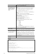
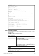
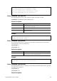
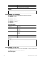
Table Of Contents
- Table of Contents
- Part I Installation
- Part II Connectivity
- Part III Wireless LAN
- Part IV VoIP
- Part V VPN
- Part VI Security
- Part VII Management
- VII-1 System Maintenance
- Web User Interface
- VII-1-1 System Status
- VII-1-2 TR-069
- VII-1-3 Administrator Password
- VII-1-4 User Password
- VII-1-5 Login Page Greeting
- VII-1-6 Configuration Backup
- VII-1-7 SysLog/Mail Alert
- VII-1-8 Time and Date
- VII-1-9 SNMP
- VII-1-10 Management
- VII-1-11 Panel Control
- VII-1-12 Self-Signed Certificate
- VII-1-12 Reboot System
- VII-1-13 Firmware Upgrade
- VII-1-14 Modem Code Upgrade
- VII-1-15 Activation
- Application Notes
- Web User Interface
- VII-2 Bandwidth Management
- VII-3 Hotspot Web Portal
- VII-4 Central Management (AP)
- VII-1 System Maintenance
- Part VIII Others
- Part IX Troubleshooting
- IX-1 Diagnostics
- Web User Interface
- IX-1-1 Dial-out Triggering
- IX-1-2 Routing Table
- IX-1-3 ARP Cache Table
- IX-1-4 IPv6 Neighbour Table
- IX-1-5 DHCP Table
- IX-1-6 NAT Sessions Table
- IX-1-7 DNS Cache Table
- IX-1-8 Ping Diagnosis
- IX-1-9 Data Flow Monitor
- IX-1-10 Traffic Graph
- IX-1-11 Trace Route
- IX-1-12 Syslog Explorer
- IX-1-13 IPv6 TSPC Status
- IX-1-14 DSL Status
- IX-1-15 DoS Flood Table
- IX-1-16 Route Policy Diagnosis
- Web User Interface
- IX-2 Checking If the Hardware Status Is OK or Not
- IX-3 Checking If the Network Connection Settings on YourComputer Is OK or Not
- IX-4 Pinging the Router from Your Computer
- IX-5 Checking If the ISP Settings are OK or Not
- IX-6 Problems for 3G/4G Network Connection
- IX-7 Backing to Factory Default Setting If Necessary
- IX-8 Contacting DrayTek
- IX-1 Diagnostics
- Appendix I: VLAN Applications on Vigor Router
- Part X DrayTek Tools
- Part XI Telnet Commands

Vigor2762 Series User’s Guide
715
% Username : vigor
% Password : 5678
% Call Direction : Dial-Out
% Type of Server : PPTP
% Dial to : 5.6.7.8
% Remote NEtwork IP : 192.168.1.31
% Remote NEtwork Mask : 255.255.255.0
> vpn trunk lb add comp 1 2
%% Combination VPN Load Balance profile list :
<Index> < Name > < Member1(Active)Type > <
Member2(Act
ive)Type >
1 comp 1(YES)PPTP 2(YES)P
PTP
%% Note: <Active: NO> The LAN-to-LAN Profile is disable or under Dial-In(Call
Di
rection) at present.
====================================================================
% Setting OK.
> vpn trunk bind set 1 y comp 2 192.168.10.1~192.168.10.2
192.168.99.1~192.168.99.254 1~65535 0 OFF
% VPN Load Balance Tunnel Bind Table Index[1] detail:
===========================================================
Action = ACTIVE
Trunk Profile(000) Name= comp
Binding Dial Out Index = 2
Binding Src IP = 192.168.10.1 ~ 192.168.10.2
Binding Dest IP = 192.168.99.1 ~ 192.168.99.254
Binding Dest Port = 1 ~ 65535
Binding Fragmented = NO
Binding Protocol = ANY Protocol
>
T
T
e
e
l
l
n
n
e
e
t
t
C
C
o
o
m
m
m
m
a
a
n
n
d
d
:
:
v
v
p
p
n
n
N
N
e
e
t
t
B
B
i
i
o
o
s
s
This command allows users to enable or disable NetBios for Remote Access User Accounts or
LAN-to-LAN Profile.
vpn NetBios set <H2l/L2l> <index> <Block/Pass>
S
S
y
y
n
n
t
t
a
a
x
x
D
D
e
e
s
s
c
c
r
r
i
i
p
p
t
t
i
i
o
o
n
n
Parameter Description
<H2l/L2l> H2l means Remote Access User Accounts.
L2l means LAN-to-LAN Profile.
Specify which one will be applied by NetBios.
<index> The index number of the profile.
<Block/Pass>
Pass – Have an inquiry for data transmission between the hosts
located on both sides of VPN Tunnel while connecting.
Block – When there is conflict occurred between the hosts on both
sides of VPN Tunnel in connecting, set it block data transmission of
Netbios Naming Packet inside the tunnel.
E
E
x
x
a
a
m
m
p
p
l
l
e
e
> vpn NetBios set H2l 1 Pass
% Remote Dial In Profile Index [1] :
% NetBios Block/Pass: [PASS]