Vigor2800 Series ADSL2/2+ Security Router Quick Start Guide Version: 2.
Copyright Information Copyright Declarations Copyright 2005 All rights reserved. This publication contains information that is protected by copyright. No part may be reproduced, transmitted, transcribed, stored in a retrieval system, or translated into any language without written permission from the copyright holders. Trademarks The following trademarks are used in this document: z Microsoft is a registered trademark of Microsoft Corp.
European Community Declarations Manufacturer: Address: Product: DrayTek Corp. No. 26, Fu Shing Road, HuKou County, HsinChu Industrial Park, Hsin-Chu, Taiwan 303 Vigor2800 Series Routers DrayTek Corp. declares that Vigor2800 series of routers are in compliance with the following essential requirements and other relevant provisions of R&TTE Directive 1999/5/EEC.
Table of Contents 1. Introduction........................................................................................................... 1 1.1 LED Indicators and Connectors ................................................................................................. 2 1.1.1 For Vigor2800 ............................................................................................................... 2 1.1.2 For Vigor2800G.................................................................................
1. Introduction Targeting requirement for residential, SOHO (Small Office and Home Office) and business users, the Vigor2800 series is ADSL2/2+ enabled integrated access devices. With downstream speed up to 12Mbps (ADSL2) or 24Mbps (ADSL2+), the Vigor2800 series provide exceptional bandwidth for Internet access.
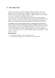
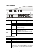
1.1 LED Indicators and Connectors 1.1.1 For Vigor2800 LAN ACT QoS Printer P2P Firewall VPN DSL Printer P1 P2 P4 PWR P3 P3 P4 P2 P1 DSL Factory Reset LED Explanation LED ACT (Activity) Status Blinking On QoS On Off On Blinking On On On Orange P2P VPN DSL Printer LAN (P1, P2, P3, P4) Green Blinking Explanation The router is powered on and running properly. The router is powered on. The QoS function is active. The QoS function is inactive. The P2P function is active.
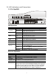
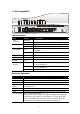
1.1.2 For Vigor2800G LAN ACT QoS Printer P2P Firewall WLAN DSL Printer P1 P2 P4 PWR LED Explanation LED Status ACT Blinking (Activity) On QoS On Off P2P On Blinking Firewall On Blinking WLAN On Blinking Off DSL On Printer On LAN (P1, P2, Orange P3, P4) Green Blinking P3 P3 P4 P2 P1 DSL Factory Reset Explanation The router is powered on and running properly. The router is powered on. The QoS function is active. The QoS function is inactive. The P2P function is active.
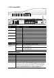
1.1.3 For Vigor2800i LAN ACT ISDN Printer P2P Firewall VPN DSL Printer P1 P2 P3 P4 PWR P3 P4 P2 P1 DSL ISDN Factory Reset LED Explanation LED Status ACT (Activity) Blinking The router is powered on and running properly. On The router is powered on. On The ISDN network is correctly setup. Blinking A successful connection on the ISDN BRI B1/B2 channel. On The P2P function is active. Blinking Starts to prohibit P2P data. VPN On The VPN tunnel is launched.
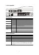
1.1.4 For Vigor2800Gi LAN ACT ISDN Printer P2P Firewall WLAN DSL Printer P1 P2 P3 P4 PWR P3 P4 P2 P1 DSL ISDN Factory Reset LED Explanation LED Status Explanation ACT (Activity) Blinking On On Blinking On Blinking On Blinking On Blinking Off On The router is powered on and running properly. The router is powered on. The ISDN network is correctly setup. A successful connection on the ISDN BRI B1/B2 channel. The P2P function is active. Starts to prohibit P2P data.
1.1.5 For Vigor2800V LED Explanation LED ACT (Activity) QoS FXS1/FXS2 VPN DSL Printer LAN (P1, P2, P3, P4) Status Blinking On On Off On Blinking On On On Orange Green Blinking Explanation The router is powered on and running properly. The router is powered on. The QoS function is active. The QoS function is inactive. The phone is off hook (the handset of phone is hanging). A phone call is incoming. The VPN tunnel is launched. The ADSL, ADSL2/2+ line is connected. The USB interface printer is ready.
1.1.6 For Vigor2800VG LED Explanation LED Status ACT Blinking (Activity) On QoS On Off FXS1/FXS2 On WLAN DSL Printer LAN (P1, P2, P3, P4) Blinking On Blinking Off On On Orange Green Blinking Explanation The router is powered on and running properly. The router is powered on. The QoS function is active. The QoS function is inactive. The phone is off hook (the handset of phone is hanging). A phone call is incoming. Wireless access point is ready. Wireless traffic goes through.
1.1.7 For Vigor2800VGi Phone ACT LAN ISDN FXS1 FXS2 WLAN DSL Printer Printer PWR FXS2 FXS1 P1 P2 P4 P3 P3 P4 P2 P1 DSL ISDN Factory Reset LED Explanation LED Status Explanation ACT (Activity) Blinking On On Blinking On The router is powered on and running properly. The router is powered on. The ISDN network is correctly setup. A successful connection on the ISDN BRI B1/B2 channel. The phone is off hook (the handset of phone is hanging).
1.
This page is left blank.
2. Installing Your Vigor Router This section will guide you to install the router through hardware connection and configure the router’s settings through web browser. 2.1 Hardware Installation Before starting to configure the router, you have to connect your devices correctly. 1. Connect the DSL interface to the external ADSL splitter with an ADSL line cable. 2. Connect one port of 4-port switch to your computer with a RJ-45 cable. This device allows you to connect 4 PCs directly. 3.
This page is left blank.
3. Configuring Web Pages 3.1 Basic Configuration The Quick Start Wizard is designed for you to easily set up your router for Internet access. You can directly access the Quick Start Wizard via Web Configurator. 1. Make sure your PC connects to the router correctly. Notice: You may either simply set up your computer to get IP dynamically from the router or set up the IP address of the computer to be the same subnet as the default IP address of Vigor router 192.168.1.1.
4. Enter the login password on the field of New Password and retype it on the field of Retype New Password. Then click Next to continue. 5. On the next page as shown below, please select the appropriate Internet access type according to the information from your ISP or click Auto detect button to detect the related DSL parameters automatically. Then click Next for next step.
PPPoE or PPPoA: if you click PPPoE or PPPoA as the protocol, please manually enter the Username/Password provided by your ISP. Check Always On means Internet access is always on regardless of Internet usage. Then click Next. Besides, the protocol set here can be reviewed in the section of DSL Modem Settings – Encapsulation on the web page of Internet Access – PPPoE/PPPoA. 1483 Bridged: if you click 1483 Bridged, you will get the following page.
1483 Routed IP: if you click 1483 Routed IP, you will get the following page. Please type in all the information originally provided by your ISP. Then click Next for next step. Besides, the protocol set here can be reviewed in the section of DSL Modem Settings – Encapsulation on the web page of Internet Access – MPoA (1483/2684). 6. Now you can see the following screen. It indicates that the setup is complete. Different types of connection modes will have different summary.
3.2 Wireless LAN Settings For the user of Vigor2800/2800V, please skip this section. For operating Vigor2800G/VG Series well, it is necessary for you to set the wireless LAN settings for using wireless function. Please read the following section carefully for configuring the settings for this router. (The default value of Frequency Domain was set by factory depends on the reselling region.) 3.2.
3.2.2 General Settings 1. On the Wireless LAN group, select General Settings. The following page will be shown. 2. Check the box Enable Wireless LAN to enable the wireless function. 3. Select an appropriate wireless mode. The router can connect to IEEE802.11b (2.4MHz), Mixed (11b+11g+SuperG) IEEE802.11g (5MHz) and SuperG stations simultaneously. This is default settings. Choose this mode if you have no idea to change the mode. The router can connect to IEEE802.11b and IEEE802.
3.2.3 Security Settings 1. On the Wireless LAN group, select Security Settings. 2. Select an appropriate encryption mode to improve the security and privacy of your wireless data packets. Disable Turn off the encryption mechanism. For the security of your router, please select any one of the encryption mode here. WEP Only Accepts only WEP clients and the encryption key should be entered in WEP Key. WEP/802.1x Only Accept WEP clients with 802.1x authentication.
WEP/802.1x or WPA/802.1x Accept WEP or WPA clients with 802.1x authentication. Remember to select WPA type to define either Mixed or WPA2 only in the field below. Since the key will be auto-negotiated during authentication, the field of key setting below will be not available for input. WPA/PSK Only Accepts WPA clients and the encryption key should be entered in PSK. Remember to select WPA type to define either Mixed or WPA2 only in the field below. WPA/802.1x Only Accept WPA clients with 802.
4. Trouble Shooting This section will guide you to solve abnormal situations if you cannot access into the Internet after installing the router and finishing the web configuration. Please follow sections below to check your basic installation status stage by stage. ¾ Checking if the hardware status is OK or not. ¾ Checking if the network connection settings on your computer are OK or not. ¾ Pinging the router from your computer. ¾ Checking if the ISP settings are OK or not.
For Windows The example is based on Windows XP. As to the examples for other operation systems, please refer to the similar steps or find support notes in www.draytek.com. 1. Go to Control Panel and then double-click on Network Connections. 2. Right-click on Local Area Connection and click on Properties. 3. Select Internet Protocol (TCP/IP) and then click Properties.
4. Select Obtain an IP address automatically and Obtain DNS server address automatically. For MacOs 1. Double click on the current used MacOs on the desktop. 2. Open the Application folder and get into Network. 3. On the Network screen, select Using DHCP from the drop down list of Configure IPv4.
4.3 Pinging the Router from Your Computer The default gateway IP address of the router is 192.168.1.1. For some reason, you might need to use “ping” command to check the link status of the router. The most important thing is that the computer will receive a reply from 192.168.1.1. If not, please check the IP address of your computer. We suggest you setting the network connection as get IP automatically. (Please refer to the section 4.2) Please follow the steps below to ping the router correctly.
25
4.4 Checking If the ISP Settings are OK or Not Click Internet Access group and then check whether the ISP settings are set correctly. For PPPoE/PPPoA Users 1. Check if the Enable option is selected. 2. Check if Username and Password are entered with correct values that you got from your ISP.
For MPoA Users 1. Check if the Enable option for Broadband Access is selected. 2. Check if all parameters of DSL Modem Settings are entered with correct value that provided by your ISP. Especially, check if the encapsulation is selected properly or not (it should be the same with the setting on Quick Start Wizard). 3. Check if IP Address, Subnet Mask and Gateway are set correctly (must identify with the values from your ISP) if you choose Specify an IP address. 4.
Hardware Reset While the router is running (ACT LED blinking), press the Factory Reset button and hold for more than 5 seconds. When you see the ACT LED blinks rapidly, please release the button. Then, the router will restart with the default configuration. After restore the factory default setting, you can configure the settings for the router again to fit your personal request. 4.