i Vigor2860 Series Quick Start Guide
Vigor2860 Series Quick Start Guide ii
Vigor2860 Series VDSL2 Security Firewall Quick Start Guide Version: 3.0 Firmware Version: V3.7.
Copyright Information Copyright Declarations © 2015 All rights reserved. This publication contains information that is protected by copyright. No part may be reproduced, transmitted, transcribed, stored in a retrieval system, or translated into any language without written permission from the copyright holders. Trademarks The following trademarks are used in this document: Microsoft is a registered trademark of Microsoft Corp.
European Community Declarations Manufacturer: Address: Product: DrayTek Corp. No. 26, Fu Shing Road, Hukou Township, Hsinchu Industrial Park, Hsinchu County, Taiwan 303 Vigor2860 Series Router DrayTek Corp. declares that Vigor2860 Series of routers are in compliance with the following essential requirements and other relevant provisions of R&TTE 1999/5/EC, ErP 2009/125/EC and RoHS 2011/65/EU.
Vigor2860 Series Quick Start Guide iv
Table of Contents 1. Introduction ........................................................................................1 1.1 Panel Explanation ...................................................................................... 2 1.1.1 For Vigor2860 ........................................................................................... 2 1.1.2 For Vigor2860n ......................................................................................... 4 1.1.3 For Vigor2860n-plus.........................
4.6 Contacting DrayTek .................................................................................
1. Introduction Vigor2860 series is a VDSL2 router with multi-subnet for secure and efficient workgroup management. It integrates IP layer QoS, NAT session/bandwidth management to help users control works well with large bandwidth. By adopting hardware-based VPN platform and hardware encryption of AES/DES/3DES, and hardware key hash of SHA-1/MD5, the router increases the performance of VPN greatly and offers several protocols (such as IPSec/PPTP/L2TP) with up to 32 VPN tunnels.
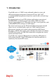
1.1 Panel Explanation 1.1.1 For Vigor2860 LED Status Explanation ACT (Activity) Blinking The router is powered on and running normally. The router is powered off. USB device is connected and ready for use. The data is transmitting. Internet connection is ready. Internet connection is not ready. The data is transmitting. The router is ready to access Internet through DSL link. Slowly: The DSL connection is ready. Quickly: The connection is training. The VPN tunnel is active.
Interface Description Factory Reset Restore the default settings. Usage: Turn on the router (ACT LED is blinking). Press the hole and keep for more than 5 seconds. When you see the ACT LED begins to blink rapidly than usual, release the button. Then the router will restart with the factory default configuration. USB Connecter for a USB device (for 3G/4G USB Modem or printer). VDSL/ADSL Connecter for accessing the Internet. WAN2 Connecter for local network devices or modem for accessing Internet.
1.1.2 For Vigor2860n LED ACT (Activity) USB WLAN WAN2 DSL Status Blinking Off On Blinking On Blinking On Off Blinking On Blinking VPN QoS WCF DoS On Off Blinking On On On Blinking LED on Connector Left On WAN2 LED Off (Giga) Blinking Right On Vigor2860 Series Quick Start Guide Explanation The router is powered on and running normally. The router is powered off. USB device is connected and ready for use. The data is transmitting. Wireless access point is ready.
LED Left GigaLAN LED 1~6 Right LED Interface Wireless LAN ON/OFF/WPS Factory Reset USB VDSL/ADSL WAN2 (Giga) GigaLAN 1-6 PWR ON/OFF Off On Off Blinking On Off The port is connected with 10/100Mbps The port is connected. The port is disconnected. The data is transmitting. The port is connected with 1000Mbps. The port is connected with 10/100Mbps Description Press the button and release it within 2 seconds. When the wireless function is ready, the green LED will be on.
1.1.3 For Vigor2860n-plus LED ACT (Activity) USB 2.4G/5G Status Blinking Off On Blinking On Blinking WAN2 DSL On Off Blinking On Blinking QoS WCF DoS On On On Blinking LED on Connector Left On WAN2 LED Off (Giga) Blinking Right On LED Off Vigor2860 Series Quick Start Guide Explanation The router is powered on and running normally. The router is powered off. USB device is connected and ready for use. The data is transmitting. Wireless access point with bandwidth of 2.4GHz/5GHz is ready.
Left GigaLAN LED 1~6 Right LED Interface Wireless LAN ON/OFF/WPS Factory Reset USB VDSL2/ADSL WAN2 (Giga) GigaLAN 1-6 PWR ON/OFF On Off Blinking On Off The port is connected. The port is disconnected. The data is transmitting. The port is connected with 1000Mbps. The port is connected with 10/100Mbps Description Press the button and release it within 2 seconds. When the wireless function is ready, the green LED will be on.
1.1.4 For Vigor2860Vn-plus LED ACT (Activity) USB 2.4G/5G Status Blinking Off On Blinking On Blinking WAN2 DSL On Off Blinking On Blinking Line On Phone (1-2) Off On Off Blinking LED on Connector On Left WAN2 LED Off Vigor2860 Series Quick Start Guide Explanation The router is powered on and running normally. The router is powered off. USB device is connected and ready for use. The data is transmitting. Wireless access point with bandwidth of 2.4GHz/5GHz is ready.
(Giga) Right LED Left GigaLAN LED 1~6 Right LED Blinking On Off On Off Blinking On Off The data is transmitting. The port is connected with 1000Mbps. The port is connected with 10/100Mbps The port is connected. The port is disconnected. The data is transmitting. The port is connected with 1000Mbps.
Interface Wireless LAN ON/OFF/WPS Factory Reset USB VDSL2/ADSL WAN2 (Giga) GigaLAN 1-6 Phone 1/2 Line PWR Vigor2860 Series Quick Start Guide Description Press the button and release it within 2 seconds. When the wireless function is ready, the green LED will be on. Press the button and release it within 2 seconds to turn off the WLAN function. When the wireless function is not ready, the LED will be off.
1.1.5 For Vigor2860ac LED ACT (Activity) USB 2.4G/5G Status Blinking Off On Blinking On Blinking WAN2 DSL On Off Blinking On Blinking QoS WCF DoS On On On Blinking LED on Connector Left On WAN2 LED Off (Giga) Blinking Right On LED Off Explanation The router is powered on and running normally. The router is powered off. USB device is connected and ready for use. The data is transmitting. Wireless access point with bandwidth of 2.4GHz/5GHz is ready.
Left GigaLAN LED 1~6 Right LED Interface Wireless LAN ON/OFF/WPS Factory Reset USB VDSL/ADSL WAN2 (Giga) GigaLAN 1-6 PWR ON/OFF Vigor2860 Series Quick Start Guide On Off Blinking On Off The port is connected. The port is disconnected. The data is transmitting. The port is connected with 1000Mbps. The port is connected with 10/100Mbps Description Press the button and release it within 2 seconds. When the wireless function is ready, the green LED will be on.
1.1.6 For Vigor2860Vac LED ACT (Activity) USB 2.4G/5G Status Blinking Off On Blinking On Blinking WAN2 DSL On Off Blinking On Blinking Line On Phone (1-2) Off On Off Blinking LED on Connector On Left WAN2 LED Off Explanation The router is powered on and running normally. The router is powered off. USB device is connected and ready for use. The data is transmitting. Wireless access point with bandwidth of 2.4GHz/5GHz is ready. It will blink slowly while wireless traffic goes through.
(Giga) Right LED Left GigaLAN LED 1~6 Right LED Vigor2860 Series Quick Start Guide Blinking On Off On Off Blinking On Off The data is transmitting. The port is connected with 1000Mbps. The port is connected with 10/100Mbps The port is connected. The port is disconnected. The data is transmitting. The port is connected with 1000Mbps.
Interface Description Wireless LAN ON/OFF/WPS Press the button and release it within 2 seconds. When the wireless function is ready, the green LED will be on. Press the button and release it within 2 seconds to turn off the WLAN function. When the wireless function is not ready, the LED will be off. When WPS function is enabled by web user interface, press this button for more than 2 seconds to wait for client’s device making network connection through WPS. Factory Reset Restore the default settings.
1.
2. Installing Your Router This section will guide you to install the router through hardware connection and configure the router’s settings through web browser. 2.1 Hardware Installation Before starting to configure the router, you have to connect your devices correctly. 1. Connect the DSL interface to the land line jack with a DSL line cable. 2. Connect the cable Modem/DSL Modem/Media Converter to the WAN port of router with Ethernet cable (RJ-45). 3.
2.2 Printer Installation You can install a printer onto the router for sharing printing. All the PCs connected this router can print documents via the router. The example provided here is made based on Windows 7. For other Windows system, please visit www.draytek.com. Before using it, please follow the steps below to configure settings for connected computers (or wireless clients). 1. Connect the printer with the router through USB port. 2. Open All Programs>>Getting Started>>Devices and Printers.
3. Click Add a printer. 4. A dialog will appear. Click Add a local printer and click Next. 5. In this dialog, choose Create a new port. In the field of Type of port, use the drop down list to select Standard TCP/IP Port. Then, click Next.
6. In the following dialog, type 192.168.1.1 (router’s LAN IP) in the field of Hostname or IP Address and type 192.168.1.1 as the Port name. Then, click Next. 7. Click Standard and choose Generic Network Card.
8. Now, your system will ask you to choose right name of the printer that you installed onto the router. Such step can make correct driver loaded onto your PC. When you finish the selection, click Next. 9. Type a name for the chosen printer. Click Next.
10. Choose Do not share this printer and click Next. 11. Then, in the following dialog, click Finish.
12. The new printer has been added and displayed under Printers and Faxes. Click the new printer icon and click Printer server properties. 13. Edit the property of the new printer you have added by clicking Configure Port.
14. Select "LPR" on Protocol, type p1 (number 1) as Queue Name. Then click OK. Next please refer to the red rectangle for choosing the correct protocol and LPR name. The printer can be used for printing now. Most of the printers with different manufacturers are compatible with vigor router. Note 1: Some printers with the fax/scanning or other additional functions are not supported. If you do not know whether your printer is supported or not, please visit www.draytek.com to find out the printer list.
Then, click the What types of printers are compatible with Vigor router? link. Note 2: Vigor router supports printing request from computers via LAN ports but not WAN port.
This page is left blank.
3. Quick Setup To access Internet, please finish basic configuration after completing the hardware installation. 3.1 Accessing Web User Interface 1. Make sure your PC connects to the router correctly. Notice: You may either simply set up your computer to get IP dynamically from the router or set up the IP address of the computer to be the same subnet as the default IP address of Vigor router 192.168.1.1. For the detailed information, please refer to the later section - Trouble Shooting of the guide. 2.
4. The web page can be logged out according to the chosen condition. The default setting is Auto Logout, which means the web configuration system will logout after five minutes without any operation. Change the setting for your necessity. 3.2 Basic Configuration – Quick Start Wizard The Quick Start Wizard is designed for you to easily set up your router for Internet access. You can directly access Wizards>>Quick Start Wizard via Web User Interface.
If your router can be under an environment with high speed NAT, the configuration provide here can help you to deploy and use the router quickly. The first screen of Quick Start Wizard is entering login password. After typing the password, please click Next. On the next page as shown below, please select the WAN interface that you use. If DSL interface is used, please choose WAN1; if Ethernet interface is used, please choose WAN2; if 3G USB modem is used, please choose WAN3 or WAN4.
3.2.1 For WAN1 (ADSL/VDSL2) WAN1 is specified for ADSL or VDSL connection. Click Next to go to the following page. You have to select the appropriate Internet access type according to the information from your ISP. For example, you should select PPPoE mode if the ISP provides you PPPoE interface. In addition, the field of For ADSL Only will be available only when ADSL is detected. Then click Next for next step.
PPPoE/PPPoA 1. Choose WAN1 as WAN Interface and click the Next button; you will get the following page. 2. After finished the above settings, simply click Next.
3. Please manually enter the Username/Password provided by your ISP. Then click Next for viewing summary of such connection. 4. Click Finish. A page of Quick Start Wizard Setup OK!!! will appear. Then, the system status of this protocol will be shown. 5. Now, you can enjoy surfing on the Internet. MPoA / Static or Dynamic IP 1. Choose WAN1 as WAN Interface and click the Next button; you will get the following page.
2. Please type in the IP address/mask/gateway information originally provided by your ISP. Then click Next for viewing summary of such connection. 3. Click Finish. A page of Quick Start Wizard Setup OK!!! will appear. Then, the system status of this protocol will be shown. 4. Now, you can enjoy surfing on the Internet.
3.2.2 For WAN2 (Ethernet) WAN2 is dedicated to physical mode in Ethernet. If you choose WAN2, please specify physical type. Then, click Next. On the next page as shown below, please select the appropriate Internet access type according to the information from your ISP. For example, you should select PPPoE mode if the ISP provides you PPPoE interface. Then click Next for next step. PPPoE 1. Choose WAN2 as the WAN Interface and click the Next button.
2. Click PPPoE as the Internet Access Type. Then click Next to continue. 3. Please manually enter the Username/Password provided by your ISP. Click Next for viewing summary of such connection. 4. Click Finish. A page of Quick Start Wizard Setup OK!!! will appear. Then, the system status of this protocol will be shown. 5. Now, you can enjoy surfing on the Internet.
PPTP/L2TP 1. Choose WAN2 as the WAN Interface and click the Next button. The following page will be open for you to specify Internet Access Type. 2. Click PPTP/L2TP as the Internet Access Type. Then click Next to continue.
3. Please type in the IP address/mask/gateway information originally provided by your ISP. Then click Next for viewing summary of such connection. 4. Click Finish. A page of Quick Start Wizard Setup OK!!! will appear. Then, the system status of this protocol will be shown. 5. Now, you can enjoy surfing on the Internet.
Static IP 1. Choose WAN2 as the WAN Interface and click the Next button. The following page will be open for you to specify Internet Access Type. 2. Click Static IP as the Internet Access type. Simply click Next to continue.
3. Please type in the IP address information originally provided by your ISP. Then click Next for next step. 4. Click Finish. A page of Quick Start Wizard Setup OK!!! will appear. Then, the system status of this protocol will be shown. 5. Now, you can enjoy surfing on the Internet.
DHCP 1. Choose WAN2 as WAN Interface and click the Next button. The following page will be open for you to specify Internet Access Type. 2. Click DHCP as the Internet Access type. Simply click Next to continue.
3. After finished the settings above, click Next for viewing summary of such connection. 4. Click Finish. A page of Quick Start Wizard Setup OK!!! will appear. Then, the system status of this protocol will be shown. 5. Now, you can enjoy surfing on the Internet.
3.2.3 For WAN3/WAN4 (USB) 1. Choose WAN3/WAN4 as WAN Interface. 2. Then, click Next for getting the following page.
3. After finished the settings above, click Next for viewing summary of such connection. 4. Click Finish. A page of Quick Start Wizard Setup OK!!! will appear. Then, the system status of this protocol will be shown. 5. Now, you can enjoy surfing on the Internet.
3.3 Wireless Configuration For the user of Vigor2860, please skip this section. For operating Vigor2860n/Vigor2860n-plus/Vigor2860Vn-plus/ Vigor2860ac/ Vigor2860Vac series well, it is necessary for you to set the wireless LAN settings for using wireless function. Please read the following section carefully for configuring the settings for this router. (The default value of Frequency Domain was set by factory depends on the reselling region.) 3.3.
3.3.2 General Setup 1. On the Wireless LAN(2.4GHz or 5GHz) group, select General Setup. The following page will be shown. 2. Check Enable Wireless LAN to enable the wireless function. 3. Choose Mixed (11b+11g+11n)/Mixed (11a+11n+11c) mode. Note: In which, 802.11b/g operates on 2.4G band, 802.11a operates on 5G band, 802.11n operates on either 2.4G or 5G band, and 802.11ac operates on 5G band only. 4. Type in the name of the SSID. The default name for SSID is DrayTek.
3.3.3 Security Settings 1. On the Wireless LAN group, select Security. 2. The default security mode is Mixed (WPA+WPA2)/PSK. For the wireless client who wants to access into Internet through such router, please input the default PSK value for connection. Default Pre-Shared Key (PSK) with 13 ASCII characters is provided and stated on the label pasted on the bottom of the router. 3. Click OK to save settings.
3.4 Registering Vigor Router You have finished the configuration of Quick Start Wizard and you can surf the Internet at any time. Now it is the time to register your Vigor router to MyVigor website for getting more service. Please follow the steps below to finish the router registration. 1. Please login the web configuration interface of Vigor router by typing “admin/admin” as User Name / Password. 2. Click Support Area>>Production Registration from the home page. 3.
If you haven’t an accessing account, please refer to section 4.9 Creating an Account for MyVigor on User’s Guide to create your own one. Please read the articles on the Agreement regarding user rights carefully while creating a user account. 4. The following page will be displayed after you logging in MyVigor. From this page, please click Add or Product Registration. 5.
6. When the following page appears, your router information has been added to the database. 7. After clicking OK, you will see the following page.
This page is left blank.
4. Trouble Shooting This section will guide you to solve abnormal situations if you cannot access into the Internet after installing the router and finishing the web configuration. Please follow sections below to check your basic installation status stage by stage. Checking if the hardware status is OK or not. Checking if the network connection settings on your computer are OK or not. Pinging the router from your computer. Checking if the ISP settings are OK or not.
4.2 Checking If the Network Connection Settings on Your Computer Is OK or Not Sometimes the link failure occurs due to the wrong network connection settings. After trying the above section, if the link is stilled failed, please do the steps listed below to make sure the network connection settings is OK. For Windows The example is based on Windows 7. As to the examples for other operation systems, please refer to the similar steps or find support notes in www.draytek.com. 1.
4. Select Internet Protocol Version 4 (TCP/IP) and then click Properties. 5. Select Obtain an IP address automatically and Obtain DNS server address automatically. Finally, click OK.
For Mac OS 1. Double click on the current used Mac OS on the desktop. 2. Open the Application folder and get into Network. 3. On the Network screen, select Using DHCP from the drop down list of Configure IPv4.
4.3 Pinging the Router from Your Computer The default gateway IP address of the router is 192.168.1.1. For some reason, you might need to use “ping” command to check the link status of the router. The most important thing is that the computer will receive a reply from 192.168.1.1. If not, please check the IP address of your computer. We suggest you setting the network connection as get IP automatically. (Please refer to the section 4.2) Please follow the steps below to ping the router correctly.
For Mac OS (Terminal) 1. Double click on the current used Mac OS on the desktop. 2. Open the Application folder and get into Utilities. 3. Double click Terminal. The Terminal window will appear. 4. Type ping 192.168.1.1 and press [Enter]. If the link is OK, the line of “64 bytes from 192.168.1.1: icmp_seq=0 ttl=255 time=xxxx ms” will appear. 4.4 Checking If the ISP Settings are OK or Not If WAN connection cannot be up, check if the LEDs (according to the LED explanations listed on section 1.
When the LEDs are on and correct, yet the WAN connection still cannot be up, please: Open WAN >> Internet Access page and then check whether the ISP settings are set correctly. Click Details Page of WAN1-WAN4 to review the settings that you configured previously. 4.5 Backing to Factory Default Setting If Necessary Sometimes, a wrong connection can be improved by returning to the default settings. Try to reset the router by software or hardware..
Software Reset You can reset the router to factory default via Web page. Go to System Maintenance and choose Reboot System on the web page. The following screen will appear. Choose Using factory default configuration and click Reboot Now. After few seconds, the router will return all the settings to the factory settings. Hardware Reset While the router is running (ACT LED blinking), press the RST button and hold for more than 5 seconds. When you see the ACT LED blinks rapidly, please release the button.
After restore the factory default setting, you can configure the settings for the router again to fit your personal request. 4.6 Contacting DrayTek If the router still cannot work correctly after trying many efforts, please contact your dealer for further help right away. For any questions, please feel free to send e-mail to support@draytek.com.