VigorPro 5510 Series Unified Threat Management User’s Guide Version: 2.1 Firmware: V3.3.4 Date: 08/06/2010 Copyright 2010 All rights reserved. This publication contains information that is protected by copyright. No part may be reproduced, transmitted, transcribed, stored in a retrieval system, or translated into any language without written permission from the copyright holders. The scope of delivery and other details are subject to change without prior notice.
VigorPro5510 Series User’s Guide iii
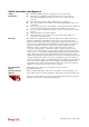
Safety Instructions and Approval Safety Instructions Warranty z z Read the installation guide thoroughly before you set up the router. The router is a complicated electronic unit that may be repaired only be authorized and qualified personnel. Do not try to open or repair the router yourself. z Do not place the router in a damp or humid place, e.g. a bathroom. z The router should be used in a sheltered area, within a temperature range of +5 to +40 Celsius.
European Community Declarations Manufacturer: Address: Product: DrayTek Corp. No. 26, Fu Shing Road, HuKou Township, HsinChu Industrial Park, Hsin-Chu, Taiwan 303 VigorPro 5510 DrayTek Corp. declares that VigorPro 5510 Series is in compliance with the following essential requirements and other relevant provisions of R&TTE Directive 1999/5/EEC.
Table of Contents 1 Preface ...............................................................................................................1 1.1 Web Configuration Buttons Explanation ................................................................................. 1 1.2 LED Indicators and Connectors .............................................................................................. 2 1.2.1 For VigorPro 5510 ........................................................................................
3.4.1 Basics for Firewall........................................................................................................... 64 3.4.2 General Setup................................................................................................................. 66 3.4.3 Filter Setup ..................................................................................................................... 71 3.4.4 DoS Defense ..................................................................................
3.12.1 Basic Concept............................................................................................................. 185 3.12.2 General Setup............................................................................................................. 185 3.12.3 Dial to a Single ISP/Dial to Dual ISPs ........................................................................ 185 3.12.4 Virtual TA .......................................................................................................
4.2 Creating and Activating an Account from Router Web Configurator................................... 249 4.3 Registering Your Vigor Router ............................................................................................ 254 4.4 Activating Anti-Virus/Anti-Intrusion/Anti-Spam/WCF Service .............................................. 257 4.4.1 For Anti-Virus and Anti-Intrusion Service ..................................................................... 257 4.4.2 For Anti-Spam Service...........
1 Preface VigorPro 5510 is a UTM router with dual-WAN interface. It provides policy-based load-balance, fail-over and BoD (Bandwidth on Demand), also it integrates IP layer QoS, NAT session/bandwidth management to help users control works well with large bandwidth.
1.2 LED Indicators and Connectors Before you use the Vigor router, please get acquainted with the LED indicators and connectors first. 1.2.1 For VigorPro 5510 LED Status Explanation ACT (Activity) Blinking Off On (Yellow) On (Yellow) On On Blinking On On The router is powered on and running normally. The router is powered off. The anti-intrusion function is enabled. IDP (Intrusion Detection and Prevention) Virus DMZ USB Monitor CSM The anti-virus function is enabled.
WAN(1/2) LAN/Monitor LAN (1-4) USB Connecter for remote networked devices. Connecter for local networked devices. Connecter for local networked devices. Connecter for a USB device. Connecter for a power cord with 100-240VAC (inlet). Power Switch. “1” is ON; “0” is OFF.
1.2.2 For VigorPro 5510Gi LED Status Explanation ACT (Activity) Blinking Off On (Yellow) On (Yellow) On On Blinking On Blinking Off On On The router is powered on and running normally. The router is powered off. The anti-intrusion function is enabled. IDP (Intrusion Detection and Prevention) Virus DMZ USB WLAN Monitor CSM The anti-virus function is enabled. DMZ Host is specified in certain site. A USB device is connected and active. The data is transmitting. Wireless access point is ready.
ISDN WAN(1/2) LAN/Monitor LAN (1-4) USB configuration. Connecter for ISDN line. Connecter for remote networked devices. Connecter for local networked devices. Connecter for local networked devices. Connecter for a USB device. Connecter for a power cord with 100-240VAC (inlet). Power Switch. “1” is ON; “0” is OFF.
1.3 Hardware Installation Before starting to configure the router, you have to connect your devices correctly. 1. Connect a cable Modem/DSL Modem/Media Converter (depends on your requirement) to any WAN port of router with Ethernet cable (RJ-45). The WAN1/WAN2 LED (Left or Right) will light up according to the speed (100 or 10) of the device that it connected. 2.
1.4 Printer Installation You can install a printer onto the router for sharing printing. All the PCs connected this router can print documents via the router. The example provided here is made based on Windows XP/2000. For Windows 98/SE, please visit www.draytek.com. Before using it, please follow the steps below to configure settings for connected computers (or wireless clients). 1. Connect the printer with the router through USB/parallel port. 2. Open Start->Settings-> Printer and Faxes.
3. Open File->Add a New Computer. A welcome dialog will appear. Please click Next. 4. Click Local printer attached to this computer and click Next. 5. In this dialog, choose Create a new port Type of port and use the drop down list to select Standard TCP/IP Port. Click Next.
6. In the following dialog, type 192.168.1.1 (router’s LAN IP) in the field of Printer Name or IP Address and type IP_192.168.1.1 as the port name. Then, click Next. 7. Click Standard and choose Generic Network Card. 8. Then, in the following dialog, click Finish.
9. Now, your system will ask you to choose right name of the printer that you installed onto the router. Such step can make correct driver loaded onto your PC. When you finish the selection, click Next. 10. For the final stage, you need to go back to Control Panel-> Printers and edit the property of the new printer you have added. 11. Select "LPR" on Protocol, type p1 (number 1) as Queue Name. Then click OK. Next please refer to the red rectangle for choosing the correct protocol and UPR name.
Note 1: Some printers with the fax/scanning or other additional functions are not supported. If you do not know whether your printer is supported or not, please visit www.draytek.com to find out the printer list. Open Support >FAQ; find out the link of Printer Server and click it; then click the What types of printers are compatible with Vigor router? link. Note 2: Vigor router supports printing request from computers via LAN ports but not WAN port.
This page is left blank.
2 Configuring Basic Settings For use the router properly, it is necessary for you to change the password of web configuration for security and adjust primary basic settings. This chapter explains how to setup a password for an administrator and how to adjust basic settings for accessing Internet successfully. Be aware that only the administrator can change the router configuration. 2.
3. Now, the Main Screen will pop up. Note: The home page will change slightly in accordance with the router you have. 4. Go to System Maintenance page and choose Administrator Password. 5. Enter the login password (the default is blank) on the field of Old Password. Type a new one in the field of New Password and retype it on the field of Confirm New Password. Then click OK to continue. 6. Now, the password has been changed.
2.2 Quick Start Wizard If your router can be under an environment with high speed NAT, the configuration provide here can help you to deploy and use the router quickly. The first screen of Quick Start Wizard is entering login password. After typing the password, please click Next. On the next page as shown below, please select the WAN interface that you use. Choose Auto negotiation as the physical type for your router. Then click Next for next step.
In the Quick Start Wizard, you can configure the router to access the Internet with different protocol/modes such as PPPoE, PPTP, Static IP or DHCP. The router supports the DSL WAN interface for Internet access. 2.2.1 PPPoE PPPoE stands for Point-to-Point Protocol over Ethernet. It relies on two widely accepted standards: PPP and Ethernet. It connects users through an Ethernet to the Internet with a common broadband medium, such as a single DSL line, wireless device or cable modem.
Click Finish. A page of Quick Start Wizard Setup OK!!! will appear. Then, the system status of this protocol will be shown.
2.2.2 PPTP Click PPTP as the protocol. Type in all the information that your ISP provides for this protocol. Click Next for viewing summary of such connection. Click Finish. A page of Quick Start Wizard Setup OK!!! will appear. Then, the system status of this protocol will be shown.
2.2.3 Static IP Click Static IP as the protocol. Type in all the information that your ISP provides for this protocol. After finishing the settings in this page, click Next to see the following page. Click Finish. A page of Quick Start Wizard Setup OK!!! will appear. Then, the system status of this protocol will be shown.
2.2.4 DHCP Click DHCP as the protocol. Type in all the information that your ISP provides for this protocol. After finishing the settings in this page, click Next to see the following page. Click Finish. A page of Quick Start Wizard Setup OK!!! will appear. Then, the system status of this protocol will be shown.
2.3 Service Activation Wizard 1. Open Service Activation Wizard. 2. The screen of Service Activation Wizard will be shown as follows. Choose the one you need and click Next. In this case, we choose to activate free trail edition. Free trial edition: if it is the first time that you register the service, please use the option. Formal edition with license key: you can extend the license valid time manually.
3. In the following page, you can activate the AV/AI, AS and/or Web content filter service at the same time or individually. When you finish the selection, please click Next. 4. Setting confirmation page will be displayed as follows, please click Next. 5. Wait for a moment till the following page appears. When such page appears, you can enable or disable these services for your necessity. Then, click Finish.
6. Now, the web page will display the service(s) with valid time that you have activated according to your selection(s). 7. Open Defense configuration >>Activation to check the services status.
If you need to extend the license valid time, you can also use the Service Activation Wizard again to reach your goal by clicking the radio button of Formal edition with license key and clicking Next.
2.4 Online Status The online status shows the system status, WAN status, ADSL Information and other status related to this router within one page. If you select PPPoE/PPTP as the protocol, you will find out a link of Dial PPPoE/PPPoA or Drop PPPoE/PPPoA in the Online Status web page.
Online status for DHCP Detailed explanation is shown below: Primary DNS Displays the IP address of the primary DNS. Secondary DNS Displays the IP address of the secondary DNS. LAN Status IP Address Displays the IP address of the LAN interface. TX Packets Displays the total transmitted packets at the LAN interface. RX Packets Displays the total number of received packets at the LAN interface. WAN1/2 Status Line Displays the physical connection (Ethernet) of this interface.
2.5 Saving Configuration Each time you click OK on the web page for saving the configuration, you can find messages showing the system interaction with you. Ready indicates the system is ready for you to input settings. Settings Saved means your settings are saved once you click Finish or OK button.
28 VigorPro5510 Series User’s Guide
3 Advanced Web Configuration After finished basic configuration of the router, you can access Internet with ease. For the people who want to adjust more setting for suiting his/her request, please refer to this chapter for getting detailed information about the advanced configuration of this router. As for other examples of application, please refer to chapter 4. 3.1 WAN Quick Start Wizard offers user an easy method to quick setup the connection mode for the router.
3.1.2 Network Connection by 3G USB Modem For 3G mobile communication through Access Point is popular more and more, VigorPro5510 adds the function of 3G network connection for such purpose. By connecting 3G USB Modem to the USB port of VigorPro5510, it can support HSDPA/UMTS/EDGE/GPRS/GSM and the future 3G standard (HSUPA, etc).
Enable Choose Yes to invoke the settings for this WAN interface. Choose No to disable the settings for this WAN interface. Display Name Type the description for the WAN1/WAN2 interface. Physical Mode For WAN1, the physical connection is done and fixed through Ethernet port; yet the physical connection for WAN2 is done through an Ethernet port (P1) or USB port. You cannot change it. To use 3G network connection through 3G USB Modem, choose 3G USB Modem as the physical mode in WAN2.
Load Balance Mode If you know the practical bandwidth for your WAN interface, please choose the setting of According to Line Speed. Otherwise, please choose Auto Weigh to let the router reach the best load balance. Line Speed If your choose According to Line Speed as the Load Balance Mode, please type the line speed for downloading and uploading through WAN1/WAN2. The unit is kbps.
3.1.4 Internet Access For the router supports dual WAN function, the users can set different WAN settings (for WAN1/WAN2) for Internet Access. Due to different physical mode for WAN1 and WAN2, the Access Mode for these two connections also varies slightly. Index It shows the WAN modes that this router supports. WAN1 is the default WAN interface for accessing into the Internet. WAN2 is the optional WAN interface for accessing into the Internet when WAN 1 is inactive for some reason.
accessing the page to configure the settings. There are three access modes provided for PPPoE, Static or Dynamic IP and PPTP. Details Page This button will open different web page according to the access mode that you choose in WAN1 or WAN2. Details Page for PPPoE To use PPPoE as the accessing protocol of the internet, please choose Internet Access from WAN menu. Then, select PPPoE mode for WAN. The following web page will be shown. PPPoE Client Mode Click Enable for activating this function.
in Application >> Schedule web page and you can use the number that you have set in that web page. ISDN Dial Backup Setup This setting is available for the routers supporting ISDN function only. Before utilizing the ISDN dial backup feature, you must create a dial backup profile first. Please click Internet Access Setup > Dialing to a Single ISP to enter the backup profile. This setting is available for i model only.
Fixed IP – Click Yes to use this function and type in a fixed IP address in the box of Fixed IP Address. Default MAC Address – You can use Default MAC Address or specify another MAC address by typing on the boxes of MAC Address for the router. Specify a MAC Address – Type the MAC address for the router manually. After finishing all the settings here, please click OK to activate them.
Static or Dynamic IP (DHCP Client) Click Enable for activating this function. If you click Disable, this function will be closed and all the settings that you adjusted in this page will be invalid. ISDN Dial Backup Setup This setting is available for the routers supporting ISDN function only. Before utilizing the ISDN dial backup feature, you must create a dial backup profile first. Please click Internet Access Setup > Dialing to a Single ISP to enter the backup profile.
Connection because some ISPs will drop connections if there is no traffic within certain periods of time. Check Enable PING to keep alive box to activate this function. PING to the IP - If you enable the PING function, please specify the IP address for the system to PING it for keeping alive. PING Interval - Enter the interval for the system to execute the PING operation.
Specify an IP address – Click this radio button to specify some data if you want to use Static IP mode. IP Address: Type the IP address. Subnet Mask: Type the subnet mask. Gateway IP Address: Type the gateway IP address. Default MAC Address: Click this radio button to use default MAC address for the router. Specify a MAC Address: Some Cable service providers specify a specific MAC address for access authentication.
This setting is available for i model only. Due to the absence of the ISDN interface in some models, the ISDN dial backup feature and its associated setup options are not available to them. Please refer to the previous part for further information. None - Disable the backup function. Packet Trigger -The backup line is not on until a packet from a local host triggers the router to establish a connection. PPP Setup PPP Authentication - Select PAP only or PAP or CHAP for PPP.
Default MAC Address – Click this radio button to use default MAC address for the router. Specify a MAC Address - Some Cable service providers specify a specific MAC address for access authentication. In such cases you need to click the Specify a MAC Address and enter the MAC address in the MAC Address field. WAN IP Network Settings Obtain an IP address automatically – Click this button to obtain the IP address automatically. Specify an IP address – Click this radio button to specify some data.
Index (1-15) Set the PCs on LAN to work at certain time interval only. You may choose up to 4 schedules out of the 15 schedules pre-defined in Applications >> Schedule setup. The default setting of this field is blank and the function will always work. 3.1.5 Load-Balance Policy This router supports the function of load balancing. It can assign traffic with protocol type, IP address for specific host, a subnet of hosts, and port range to be allocated in WAN1 or WAN2 interface.
WAN Use the drop-down menu to change the WAN interface for such index. Src IP Start Displays the IP address for the start of the source IP. Src IP End Displays the IP address for the end of the source IP. Dest IP Start Displays the IP address for the start of the destination IP. Dest IP End Displays the IP address for the end of the destination IP. Dest Port Start Displays the IP address for the start of the destination port.
You can check the box of Auto failover to other WAN to make a backup WAN connection if the selected WAN interface fails to connect to Internet. Src IP Start Type the source IP start for the specified WAN interface. Src IP End Type the source IP end for the specified WAN interface. If this field is blank, it means that all the source IPs inside the LAN will be passed through the WAN interface. Dest IP Start Type the destination IP start for the specified WAN interface.
3.2 LAN Local Area Network (LAN) is a group of subnets regulated and ruled by router. The design of network structure is related to what type of public IP addresses coming from your ISP. Note: VLAN menu item is only available for VigorPro 5510. 3.2.1 Basics of LAN The most generic function of Vigor router is NAT. It creates a private subnet of your own.
What is Routing Information Protocol (RIP) Vigor router will exchange routing information with neighboring routers using the RIP to accomplish IP routing. This allows users to change the information of the router such as IP address and the routers will automatically inform for each other. What is Static Route When you have several subnets in your LAN, sometimes a more effective and quicker way for connection is the Static routes function rather than other method.
3.2.2 General Setup This page provides you the general settings for LAN. Click LAN to open the LAN settings page and choose General Setup. 1st IP Address Type in private IP address for connecting to a local private network (Default: 192.168.1.1). 1st Subnet Mask Type in an address code that determines the size of the network. (Default: 255.255.255.0/ 24) For IP Routing Usage Click Enable to invoke this function. The default setting is Disable.
Start IP Address: Enter a value of the IP address pool for the DHCP server to start with when issuing IP addresses. If the 2nd IP address of your router is 220.135.240.1, the starting IP address must be 220.135.240.2 or greater, but smaller than 220.135.240.254. IP Pool Counts: Enter the number of IP addresses in the pool. The maximum is 10. For example, if you type 3 and the 2nd IP address of your router is 220.135.240.1, the range of IP address by the DHCP server will be from 220.135.240.2 to 220.135.240.
DHCP Server IP Address for Relay Agent - Set the IP address of the DHCP server you are going to use so the Relay Agent can help to forward the DHCP request to the DHCP server. DNS Server Configuration DNS stands for Domain Name System. Every Internet host must have a unique IP address, also they may have a human-friendly, easy to remember name such as www.yahoo.com. The DNS server converts the user-friendly name into its equivalent IP address.
3.2.3 Static Route Go to LAN to open setting page and choose Static Route. Index The number (1 to 32) under Index allows you to open next page to set up static route. Destination Address Displays the destination address of the static route. Status Displays the status of the static route. Viewing Routing Table Displays the routing table for your reference.
Before setting Static Route, user A cannot talk to user B for Router A can only forward recognized packets to its default gateway Main Router. Go to LAN page and click General Setup, select 1st Subnet as the RIP Protocol Control. Then click the OK button. Note: There are two reasons that we have to apply RIP Protocol Control on 1st Subnet. The first is that the LAN interface can exchange RIP packets with the neighboring routers via the 1st subnet (192.168.1.0/24).
2. Return to Static Route Setup page. Click on another Index Number to add another static route as show below, which regulates all packets destined to 211.100.88.0 will be forwarded to 192.168.1.3. 3. Go to Diagnostics and choose Routing Table to verify current routing table. 3.2.4 VLAN Virtual LAN function provides you a very convenient way to manage hosts by grouping them based on the physical port. You can also manage the in/out rate of each port. Go to LAN page and select VLAN.
2. After checking the box to enable VLAN function, you will check the table according to the needs as shown below. To remove VLAN, uncheck the needed box and click OK to save the results. 3.2.5 Bind IP to MAC This function is used to bind the IP and MAC address in LAN to have a strengthen control in network. When this function is enabled, all the assigned IP and MAC address binding together cannot be changed. If you modified the binding IP or MAC address, it might cause you not access into the Internet.
Enable Click this radio button to invoke this function. However, IP/MAC which is not listed in IP Bind List also can connect to Internet. Disable Click this radio button to disable this function. All the settings on this page will be invalid. Strict Bind Click this radio button to block the connection of the IP/MAC which is not listed in IP Bind List. ARP Table This table is the LAN ARP table of this router. The information for IP and MAC will be displayed in this field.
Note: Before you select Strict Bind, you have to bind one set of IP/MAC address for one PC. If not, no one of the PCs can access into Internet. And the web configurator of the router might not be accessed. 3.3 NAT Usually, the router serves as an NAT (Network Address Translation) router. NAT is a mechanism that one or more private IP addresses can be mapped into a single public one. Public IP address is usually assigned by your ISP, for which you may get charged.
The port redirection can only apply to incoming traffic. To use this function, please go to NAT page and choose Port Redirection web page. The Port Redirection Table provides 20 port-mapping entries for the internal hosts. Press any number under Index to access into next page for configuring port redirection.
Enable Check this box to enable such port redirection setting. Mode Two options (Single and Range) are provided here for you to choose. To set a range for the specific service, select Range. In Range mode, if the public port (start port and end port) and the starting IP of private IP had been entered, the system will calculate and display the ending IP of private IP automatically. Service Name Enter the description of the specific network service.
You then will access the admin screen of by suffixing the IP address with 8080, e.g., http://192.168.1.1:8080 instead of port 80.
3.3.2 DMZ Host As mentioned above, Port Redirection can redirect incoming TCP/UDP or other traffic on particular ports to the specific private IP address/port of host in the LAN. However, other IP protocols, for example Protocols 50 (ESP) and 51 (AH), do not travel on a fixed port. Vigor router provides a facility DMZ Host that maps ALL unsolicited data on any protocol to a single host in the LAN.
WAN1 This page allows you to configure Private IP or Active True IP as DMZ host. WAN2 This page allows you to configure Private IP as DMZ host. Private IP If you choose Private IP as DMZ host, you can type a private IP in this box or use Choose PC button to choose the one you want. MAC Address of the True…. If you choose Active True IP as DMZ host, please type the MAC address of the one you want. If you previously have set up WAN Alias in Internet Access>>PPPoE, you will find them in Aux.
3.3.3 Open Ports Open Ports allows you to open a range of ports for the traffic of special applications. Common application of Open Ports includes P2P application (e.g., BT, KaZaA, Gnutella, WinMX, eMule and others), Internet Camera etc. Ensure that you keep the application involved up-to-date to avoid falling victim to any security exploits. Click Open Ports to open the following page: Index Indicate the relative number for the particular entry that you want to offer service in a local host.
Enable Open Ports Check to enable this entry. Comment Make a name for the defined network application/service. WAN Interface Specify the WAN interface that will be used for this entry. Local Computer Enter the private IP address of the local host or click Choose PC to select one. Choose PC Click this button and, subsequently, a window having a list of private IP addresses of local hosts will automatically pop up. Select the appropriate IP address of the local host in the list.
Protocol Display the protocol used for this address mapping. Public IP Display the public IP address selected for this entry, e.g., 172.16.3.102. Private IP Display the private IP set for this address mapping, e.g., 192.168.1.10 Mask Display the subnet mask selected for this address mapping. Status Display the status for the entry, enable or disable. Click the index number link to open the configuration page. Enable Check to enable this entry. Protocol Specify the transport layer protocol.
the IP Alias List, the Public IP setting will be empty in this field. When you click Apply, a message will appear to inform you. Private IP Assign an IP address (e.g., 192.168.1.10) or a subnet to be compared with the Public IP address for incoming packets. Subnet Mask Select a value of subnet mask for private IP address. 3.4 Firewall 3.4.
Stateful Packet Inspection (SPI) Stateful inspection is a firewall architecture that works at the network layer. Unlike legacy static packet filtering, which examines a packet based on the information in its header, stateful inspection builds up a state machine to track each connection traversing all interfaces of the firewall and makes sure they are valid. The stateful firewall of Vigor router not just examine the header information also monitor the state of the connection.
1. SYN flood attack 2. UDP flood attack 3. ICMP flood attack 4. TCP Flag scan 5. Trace route 6. IP options 7. Unknown protocol 8. Land attack 9. Smurf attack 10. SYN fragment 11. ICMP fragment 12. Tear drop attack 13. Fraggle attack 14. Ping of Death attack 15. TCP/UDP port scan Anti-Virus and Anti-Intrusion Users might have much more confidence about the security in the network for data transmission if the functions of anti-virus and anti-intrusion are activated.
Call Filter Check Enable to activate the Call Filter function. Assign a start filter set for the Call Filter. Data Filter Check Enable to activate the Data Filter function. Assign a start filter set for the Data Filter. Filter Select Pass or Block for the packets that do not match with the filter rules. IM/P2P Filter Select an IM/P2P profile for global IM/P2P application blocking. All the hosts in LAN must follow the standard configured in the IM/P2P profile selected here.
Filter web page first. For troubleshooting needs, you can specify to record information for Web Content Filter by checking the Log box. It will be sent to Syslog server. Please refer to section 3.13.4 Syslog/Mail Alert for more detailed information. Anti-Virus Select one of the anti-virus profile settings (created in Anti-Virus>>Profile Setting) for applying with this router. Please set at least one profile for anti-virus in Anti-Virus-> Profile Setting web page first.
Advance Setting Click Edit to open the following window. However, it is strongly recommended to use the default settings here. Codepage - This function is used to compare the characters among different languages. Choose correct codepage can help the system obtaining correct ASCII after decoding data from URL and enhance the correctness of URL Content Filter. The default value for this setting is ANSI 1252 Latin I. If you do not choose any codepage, no decoding job of URL will be processed.
for the router to verify if the retransmitted data is the same as the old one. Advertisement Enable – Check this box to display the words – [Powered by Draytek] on the unreachable web page Strict Security Checking For the sake of security, you might want the router executing strict security checking for data transmission. The router performance will be affected if you invoke strict security checking. Anti-Virus – Check this box to execute the critical checking for virus.
3.4.3 Filter Setup Click Firewall and click Filter Setup to open the setup page. To edit or add a filter, click on the set number to edit the individual set. The following page will be shown. Each filter set contains up to 7 rules. Click on the rule number button to edit each rule. Check Active to enable the rule. Filter Rule Click a button numbered (1 ~ 7) to edit the filter rule. Click the button will open Edit Filter Rule web page. For the detailed information, refer to the following page.
Check to enable the Filter Rule Check this box to enable the filter rule. Comments Enter filter set comments/description. Maximum length is 14character long. Index (1-15) Set PCs on LAN to work at certain time interval only. You may choose up to 4 schedules out of the 15 schedules pre-defined in Applications >> Schedule setup. The default setting of this field is blank and the function will always work. Direction Set the direction of packet flow (LAN->WAN/WAN->LAN). It is for Data Filter only.
To set the IP address manually, please choose Any Address/Single Address/Range Address/Subnet Address as the Address Type and type them in this dialog. In addition, if you want to use the IP range from defined groups or objects, please choose Group and Objects as the Address Type. From the IP Group drop down list, choose the one that you want to apply. Or use the IP Object drop down list to choose the object that you want.
choose Group and Objects as the Service Type. Protocol - Specify the protocol(s) which this filter rule will apply to. Source/Destination Port (=) – when the first and last value are the same, it indicates one port; when the first and last values are different, it indicates a range for the port and available for this service type.
Filter by checking the Log box. It will be sent to Syslog server. Please refer to section Syslog/Mail Alert for more detailed information. Web Content Filter Select one of the Web Content Filter profile settings (created in CSM>> Web Content Filter Profile) for applying with this router. Please set at least one profile for anti-virus in CSM>> Web Content Filter Profile web page first. For troubleshooting needs, you can specify to record information for Web Content Filter by checking the Log box.
default value for this setting is ANSI 1252 Latin I. If you do not choose any codepage, no decoding job of URL will be processed. Please use the drop-down list to choose a codepage. If you do not have any idea of choosing suitable codepage, please open Syslog. From Codepage Information of Setup dialog, you will see the recommended codepage listed on the dialog box. Window size – It determines the size of TCP protocol (0~65535). The more the value is, the better the performance will be.
Example As stated before, all the traffic will be separated and arbitrated using on of two IP filters: call filter or data filter. You may preset 12 call filters and data filters in Filter Setup and even link them in a serial manner. Each filter set is composed by 7 filter rules, which can be further defined. After that, in General Setup you may specify one set for call filter and one set for data filter to execute first.
3.4.4 DoS Defense As a sub-functionality of IP Filter/Firewall, there are 15 types of detect/defense function in the DoS Defense setup. The DoS Defense functionality is disabled for default. Click Firewall and click DoS Defense to open the setup page. Enable Dos Defense Check the box to activate the DoS Defense Functionality. Enable SYN flood defense Check the box to activate the SYN flood defense function.
Enable PortScan detection Port Scan attacks the Vigor router by sending lots of packets to many ports in an attempt to find ignorant services would respond. Check the box to activate the Port Scan detection. Whenever detecting this malicious exploration behavior by monitoring the port-scanning Threshold rate, the Vigor router will send out a warning. By default, the Vigor router sets the threshold as 150 packets per second. Block IP options Check the box to activate the Block IP options function.
Block Unknown Protocol Check the box to activate the Block Unknown Protocol function. Individual IP packet has a protocol field in the datagram header to indicate the protocol type running over the upper layer. However, the protocol types greater than 100 are reserved and undefined at this time. Therefore, the router should have ability to detect and reject this kind of packets. Warning Messages We provide Syslog function for user to retrieve message from Vigor router.
3.5 Objects Settings For IPs in a range, service ports in a limited range and keywords usually will be applied for configuring router’s settings, we can define them with objects and bind them with groups for using conveniently. Later, we can select that object/service for applying. For example, all the IPs in the same department can be defined with an IP object (a range of IP address).
3.5.1 IP Object You can set up to 192 sets of IP Objects with different conditions. Set to Factory Default Clear all profiles. Click the number under Index column for settings in detail. Name Type a name for this profile. Maximum 15 characters are allowed. Interface Choose a proper interface (WAN, LAN or Any). For example, the Direction setting in Edit Filter Rule will ask you specify IP or IP range for WAN or LAN or any IP address.
Address Type Determine the address type for the IP address. Select Single Address if this object contains one IP address only. Select Range Address if this object contains several IPs within a range. Select Subnet Address if this object contains one subnet for IP address. Select Any Address if this object contains any IP address. Start IP Address Type the start IP address for Single Address type. End IP Address Type the end IP address if the Range Address type is selected.
3.5.2 IP Group This page allows you to bind several IP objects into one IP group. Set to Factory Default Clear all profiles. Click the number under Index column for settings in detail. Name Type a name for this profile. Maximum 15 characters are allowed. Interface Choose WAN, LAN or Any to display all the available IP objects with the specified interface.
3.5.3 Service Type Object You can set up to 96 sets of Service Type Objects with different conditions. Set to Factory Default Clear all profiles. Click the number under Index column for settings in detail. Name Type a name for this profile. Protocol Specify the protocol(s) which this profile will apply to. Source/Destination Port Source Port and the Destination Port column are available for TCP/UDP protocol. It can be ignored for other protocols. The filter rule will filter out any port number.
all the ports except the port defined here; when the first and last values are different, it indicates that all the ports except the range defined here are available for this service type. (>) – the port number greater than this value is available. (<) – the port number less than this value is available for this profile. Below is an example of service type objects settings. 3.5.4 Service Type Group This page allows you to bind several service types into one group.
Name Type a name for this profile. Available Service Type Objects You can add IP objects from IP Object page. All the available IP objects will be shown in this box. Selected Service Type Objects button to add the selected IP objects in this Click box. 3.5.5 Keyword Object You can set 200 keyword object profiles for choosing as black /white list in Anti-Spam >>Profile Setting. Set to Factory Default Clear all profiles. Click the number under Index column for setting in detail.
Name Type a name for this profile, e.g., game. Contents Type the content for such profile. For example, type gambling as Contents. When you browse the webpage, the page with gambling information will be watched out and be passed/blocked based on the configuration on Firewall settings. 3.5.6 Keyword Group This page allows you to bind several keyword objects into one group. The keyword groups set here will be chosen as black /white list in Anti-Spam >>Profile Setting.
Name Type a name for this group. Available Keyword Objects You can gather keyword objects from Keyword Object page within one keyword group. All the available Keyword objects that you have created will be shown in this box. Selected Keyword Objects Click this box. button to add the selected Keyword objects in 3.5.7 File Extension Object This page allows you to set eight profiles which will be applied in CSM>>URL Content Filter and Defense Configuration>>Anti-Virus.
Profile Name Type a name for this profile. Type a name for such profile and check all the items of file extension that will be processed in the router. Finally, click OK to save this profile.
3.5.8 IM Object This page allows you to set 32 profiles for Instant Messenger. These profiles will be applied in Firewall>>IM/P2P Filter Profile for filtering. Set to Factory Default Clear all profiles. Click the number under Profile column for configuration in details. There are several types of Instant Messenger (IM) provided here for you to choose to disallow people using. Simple check the box (es) and then click OK.
Profile Name Type a name for this profile. Type a name for such profile and check all the items that not allowed to be used in the host. Finally, click OK to save this profile.
3.5.9 P2P Object This page allows you to set 32 profiles for peer-to-peer application. These profiles will be applied in Firewall>>IM/P2P Filter Profile for filtering. Set to Factory Default Clear all profiles. Click the number under Profile column for configuration in details. There are several items for P2P protocols provided here for you to choose to disallow people using. Simple check the box (es) and then click OK.
Type a name for such profile and check all the protocols that not allowed to be used in the host. Finally, click OK to save this profile. 3.5.10 Misc Object This page allows you to set 32 profiles for miscellaneous applications. These profiles will be applied in Firewall>>IM/P2P Filter Profile for filtering. Set to Factory Default Clear all profiles. Click the number under Profile column for configuration in details.
Profile Name Type a name for this profile. Type a name for such profile and check all the protocols that not allowed to be used in the host. Finally, click OK to save this profile. 3.6 CSM CSM is an abbreviation of Content Security Management which is used to control IM/P2P usage, filter the web content and URL content to reach a goal of security management. IM/P2P Filtering As the popularity of all kinds of instant messenger application arises, communication cannot become much easier.
On the other hand, Vigor router can prevent user from accidentally downloading malicious codes from web pages. It’s very common that malicious codes conceal in the executable objects, such as ActiveX, Java Applet, compressed files, and other executable files. Once downloading these types of files from websites, you may risk bringing threat to your system. For example, an ActiveX control object is usually used for providing interactive web feature. If malicious code hides inside, it may occupy user’s system.
3.6.1 APP Enforcement Profile You can define policy profiles for IM (Instant Messenger)/P2P (Peer to Peer)/Protocol application. This page allows you to set 32 profiles for different requirements. The APP Enforcement Profile will be applied in Default Rule of Firewall>>General Setup for filtering. Set to Factory Default Clear all profiles. Profile Display the number of the profile which allows you to click to set different policy. Name Display the name of the APP Enforcement Profile.
full or partial matched with a keyword, the Vigor router will block the associated HTTP connection. For example, if you add key words such as “sex”, Vigor router will limit web access to web sites or web pages such as “www.sex.com”, ”www.backdoor.net/images/sex/p_386.html”. Or you may simply specify the full or partial URL such as “www.sex.com” or “sex.com”. Also the Vigor router will discard any request that tries to retrieve the malicious code.
configuration set in this page for URL Access Control and Web Feature will be inactive. Both:Block –The router will block all the packages that match with the conditions specified in URL Access Control and Web Feature below. When you choose this setting, both configuration set in this page for URL Access Control and Web Feature will be inactive.
Group/Object Selections – The Vigor router provides several frames for users to define keywords and each frame supports multiple keywords. The keyword could be a noun, a partial noun, or a complete URL string. Multiple keywords within a frame are separated by space, comma, or semicolon. In addition, the maximal length of each frame is 32-character long. After specifying keywords, the Vigor router will decline the connection request to the website whose URL string matched to any user-defined keyword.
provide the blocking mechanism that filters out the multimedia files downloading from web pages. Upload – Check the box to reject any file upload job. File Extension Profile – Choose one of the profiles that you configured in Object Setting>> File Extension Objects previously for passing or blocking the file downloading. 3.6.
Activate Click it to access into MyVigor for activating WCF service. Setup Query Server It is recommend for you to use the default setting, auto-selected. You need to specify a server for categorize searching when you type URL in browser based on the web content filter profile. Setup Test Server It is recommend for you to use the default setting, auto-selected. By the way, you can click the link of Test a site to verify whether it is categorized to access into the test server selected.
processing rate combining the feature of L1 and L2. Eight profiles are provided here as Web content filters. Simply click the index number under Profile to open the following web page. The items listed in Categories will be changed according to the different service providers. If you have and activate another web content filter license, the items will be changed simultaneously. All of the configuration made for web content filter will be deleted automatically.
Log None – There is no log file will be recorded for this profile. Pass – Only the log about Pass will be recorded in Syslog. Block – Only the log about Block will be recorded in Syslog. All – All the actions (Pass and Block) will be recorded in Syslog. White/Black List Enable – Activate white/black list function for such profile. Group/Object Selections – Click Edit to choose the group or object profile as the content of white/black list.
3.7 Defense Configuration This menu allows you to set profiles for, activate and upgrade the service of Anti-Intrusion/Anti-Virus in your system. 3.7.1 Anti-Intrusion Anti-Intrusion allows you to prevent the intrusion from hackers while accessing into Internet. It can detect the intrusion and execute basic defense. There are more than 200 basic rules for anti-intrusion and anti-virus for this router. To acquire more rules for anti-intrusion, it is suggested for you to register your router by entering www.
Anti-Intrusion Control Setup This field will display the signature version of this router. The default signature version is “basic”. In this version, you can modify the settings for Anti-Intrusion rules in Defense Configuration>>Anti-Intrusion >>Advanced Setup page. However, if you restart/reset the router, all the modified configurations for the rules will not be available and return to the default settings.
Enable Reset procession Click this radio button to break down the communication between your computer and specific link which might have intrusion actions. 3.7.1.2 Advanced Setup This page lists all the available types and allows you to adjust the rule setting for each type. The rules will be applied by the options chosen in the page of Defense Configuration>>Anti-Intrusion>>Basic Setup for Anti-Intrusion.
Enable Check to enable this rule. If you uncheck this box, the corresponding settings for the rule will not be executed. SID The number for each anti-intrusion rule is displayed in this field. Name A brief description name for the anti-intrusion rule is shown in this field. Click the name link to access into VigorPro website for checking the detailed information for the specified antiintrusion.
Page Type the page number in this field (if there is more than one page of anti-virus detail view displayed on this page). Then click Go to the specified page. Or you can click ⏐>, >>, << or >⏐ button on the right side of the Go button to access to the home/previous/next/end page. 3.7.2 Anti-Virus Vigor router can offer basic virus scanning, destroying and cut off the connection between questionable link and your computer for the files transmitted through specified protocol.
Profile Name Type a name for the profile. Protocol Currently, only the files transmitted through the protocols listed in this page including SMTP, POP3, IMAP, HTTP and FTP will be scanned by this router. Action Choose the action that you want to apply to the protocols of each operation. Pass - Detect if there is any virus for your reference. The system will not do any advanced action for such condition. Destroy- Destroy the infected file found by the router system.
Detect Macro Attachment The file with macro attachment will be passed/destroyed/reset under different protocols. The system will detect it automatically if you set corresponding configuration here. Detect Encrypted Zipped Files The file zipped with encryption will be detected and then be passed/destroyed/reset according to the configuration set here.
SID/NAME To find the specific type of anti-virus, you can type its SID number or name in this field if you know, and then click Search. The system will locate that rule for you. Search Click this button to find out all the virus rules related to the SID/NAME that you entered. The page of the searching result will be shown as the following picture. Click each name link to check the detailed information of the anti-virus rule.
NAME A brief description name for the anti-virus rule is shown in this field. Click the name link to access into VigorPro website for checking the detailed information for the specified anti-virus. SID The number for each anti-virus rule is displayed in this field. Page Type the page number in this field (if there is more than one page of anti-virus detail view displayed on this page). Then click Go to the specified page.
Click any number link to open the configuration page. Below is the page of File Filter Profile. The priority of each entry is determined by the index number. That is, the entry of Index 1 has the highest priority in file name filtering; the entry of Index 32 has the lowest priority in filtering. Profile Name Type a name for such profile. Priority Such item determines which profile will be executed first.
found by the router system. Non-Scan –The file will not be scanned and will not be processed by using general rules set in Anti-Virus profile. Scan – Just scan the file with name specified here which is found by the router system, and be processed by using general rules set in Anti-Virus profile. Profile – Use the drop down list to specify one profile to be executed as filtering condition. Destroy the file if the file name is over length Check this box to destroy the file with filename over 76 characters.
3.7.3 Anti-Spam Many people suffer with unwanted mails coming from everywhere. Such device offers a mechanism, named Anti-Spam, to do basic scanning for filtering unnecessary mails and sorting the mails. To activate function of Anti-Spam, you have to configure profile(s) for your computer first. 3.7.3.1 Profile Setting Open Defense Configuration>>Anti- Spam>>Profile Setting menu to access into the following page. There are sixteen profiles provided by this system for you to define.
Profile Name Type a name for such profile setting. Choose Protocol to Scan Spam Spam files usually come with protocol of SMTP or POP3. Please check the box that you want to avoid. It would be better to check both protocols. In addition, you can check Log All Mail Events to send record of all mail events to syslog. Enable SPAM Grey List Defense Grey List is a method for e-mail against spam.
emails coming from the sender, or for the emails sending out from the receiver, or for the subject with the keyword selected here. Group/Object Selections – Choose a suitable group or object for passing or blocking. Click Edit to open the following dialog. The keyword/group that you have set on Object Settings>>Keyword Object/ Object Settings>>Keyword Group will be displayed here for you to choose. Destroy Tag Message (Max 30 characters) – Type the character(s) as a tag for destroying.
shown as “***SPAM*** license page” in your mail box. Such tag can help users to identify which mail is useful or useless quickly. Reset – Choose this action to disconnect the network. It is mainly applied on SMTP server. Log - Check the box to have the process record stated on Syslog. Message - Type words which will be placed before the subject of mail and help you to identify. Clear Delete the settings configured above and reset to default settings.
White List Timeout (sec) Type the timeout for mail checking with white list. Set Click to save and invoke the timer setting. 3.7.4 Activation for Anti-Intrusion/Anti-Virus/Anti-Spam/Web-Filter Service After you have finished the profile settings, it is the time to activate the mechanism for your computer. Click Defense Configuration>>Activation to open the following page for accessing http://myvigor.draytek.com.
VigorPro5510 Series User’s Guide 121
3.7.5 AI/AV Auto Block This page can determine the block standard for data transmission based on the AI/AV auto block setting. In another word, when the host is attacked over the count number set here, the system will block the data transmission from the source IP automatically for security. Limitation List displays the specific limitations that you set in this web page. Enable/Disable Click Enable to activate AI/AV Count Setting.
Time Interval – type the time for the system to wait and execute the action of blocking, Limitation List This field displays the information for specific limitation. Specific Limitation Users can specify clients on LAN and let the router count AI/AV event in certain range by specifying start IP, end IP, AI count, AV count, time interval and etc. Start IP/End IP – Specify the range for specific limitation (starting IP and ending IP).
3.7.6 Signature Upgrade You can get the most updated signature from DrayTek’s server if the license key of anti-virus/anti-intrusion for the VigorPro 5510 is not expired. Before you upgrade the signature, please check the validation information either from WEB user interface of VigorPro 5510 or account information from www.vigorpro.com. Signature Upgrade Setting It displays the signature version for your reference.
It displays the message of signature authentication or download Signature authentication/downl procedure. oad message Upgrade Manually The buttons in this field are only available when you finished the registration and activation for new account and your router. If not, these buttons do not have any effect even if you click them. Import – You can import a saved file to manually upgrade the signature. Click Browse to choose the right file with .sig file format. Next, click Upgrade.
Upgrade Automatically Specify certain time for executing the upgrade automatically. Remember to check the Scheduled Update box to activate the time settings. Every – It means the downloading procedure will be executed automatically whenever passing through the time (hours and minutes) that you set here. Daily - It means the downloading procedure will be automatically executed every day at the time (hours and minutes) that you set here.
Below shows an example with DT-KL signature used. 3.7.7 Status This field will shows the status for the license, start date and expire date for Anti-Intrusion/Anti-Virus service. If your account or router is still not activated, the word Not Activated will be displayed here to inform you.
Below is a sample page with valid license. 3.8 Bandwidth Management Below shows the menu items for Bandwidth Management. 3.8.1 Sessions Limit A PC with private IP address can access to the Internet via NAT router. The router will generate the records of NAT sessions for such connection. The P2P (Peer to Peer) applications (e.g., BitTorrent) always need many sessions for procession and also they will occupy over resources which might result in important accesses impacted.
To activate the function of limit session, simply click Enable and set the default session limit. Enable Click this button to activate the function of limit session. Disable Click this button to close the function of limit session. Default session limit Defines the default session number used for each computer in LAN. Limitation List Displays a list of specific limitations that you set on this web page. Start IP Defines the start IP address for limit session.
In the Bandwidth Management menu, click Bandwidth Limit to open the web page. To activate the function of limit bandwidth, simply click Enable and set the default upstream and downstream limit. Enable Click this button to activate the function of limit bandwidth. Apply to 2nd Subnet – if bandwidth limit function is enabled, please check this box to apply to second subnet. Disable Click this button to close the function of limit bandwidth.
limit and RX limit. TX limit Define the limitation for the speed of the upstream. If you do not set the limit in this field, the system will use the default speed for the specific limitation you set for each index. RX limit Define the limitation for the speed of the downstream. If you do not set the limit in this field, the system will use the default speed for the specific limitation you set for each index. Add Add the specific speed limitation onto the list above.
DS node in these domains will perform the priority treatment. This is called per-hop-behavior (PHB). The definition of PHB includes Expedited Forwarding (EF), Assured Forwarding (AF), and Best Effort (BE). AF defines the four classes of delivery (or forwarding) classes and three levels of drop precedence in each class.
Enable the QoS Control The factory default for this setting is checked. Please also define which traffic the QoS Control settings will apply to. IN- apply to incoming traffic only. OUT-apply to outgoing traffic only. BOTH- apply to both incoming and outgoing traffic. Check this box and click OK, then click Setup link again. You will see the Online Statistics link appearing on this page. WAN Inbound Bandwidth It allows you to set the connecting rate of data input for WAN.
Limited_bandwidth Ratio The ratio typed here is reserved for limited bandwidth of UDP application. Online Statistics Display an online statistics for quality of service for your reference. This link will be seen only if you click OK in WAN1/WAN2 General Setup web page and click Setup again (for WAN1/WAN2) on the Bandwith Management>>Quality of Service. Edit the Class Rule for QoS The first three (Class 1 to Class 3) class rules can be adjusted for your necessity.
For adding a new rule, click Add to open the following page. ACT Check this box to invoke these settings. Local Address Click the Edit button to set the local IP address (on LAN) for the rule. Remote Address Click the Edit button to set the remote IP address (on LAN/WAN) for the rule. Edit It allows you to edit source address information. Address Type – Determine the address type for the source address. For Single Address, you have to fill in Start IP address.
Edit the Service Type for Class Rule To add a new service type, edit or delete an existed service type, please click the Edit link under Service Type field. After you click the Edit link, you will see the following page.
For adding a new service type, click Add to open the following page. Service Name Type in a new service for your request. Service Type Choose the type (TCP, UDP or TCP/UDP) for the new service. Port Configuration Click Single or Range. If you select Range, you have to type in the starting port number and the end porting number on the boxes below. Port Number – Type in the starting port number and the end porting number here if you choose Range as the type.
3.9 Applications Below shows the menu items for Applications. 3.9.1 Dynamic DNS The ISP often provides you with a dynamic IP address when you connect to the Internet via your ISP. It means that the public IP address assigned to your router changes each time you access the Internet. The Dynamic DNS feature lets you assign a domain name to a dynamic WAN IP address. It allows the router to update its online WAN IP address mappings on the specified Dynamic DNS server.
3. Domain Name Display the domain name that you set on the setting page of DDNS setup. Active Display if this account is active or inactive. View Log Display DDNS log status. Force Update Force the router updates its information to DDNS server. Select Index number 1 to add an account for the router. Check Enable Dynamic DNS Account, and choose correct Service Provider: dyndns.org, type the registered hostname: hostname and domain name suffix: dyndns.org in the Domain Name block.
4. Click OK button to activate the settings. You will see your setting has been saved. The Wildcard and Backup MX features are not supported for all Dynamic DNS providers. You could get more detailed information from their websites. Disable the Function and Clear all Dynamic DNS Accounts In the DDNS setup menu, uncheck Enable Dynamic DNS Setup, and push Clear All button to disable the function and clear all accounts from the router.
Enable Schedule Setup Check to enable the schedule. Start Date (yyyy-mm-dd) Specify the starting date of the schedule. Start Time (hh:mm) Specify the starting time of the schedule. Duration Time (hh:mm) Specify the duration (or period) for the schedule. Action Specify which action Call Schedule should apply during the period of the schedule. Force On -Force the connection to be always on. Force Down -Force the connection to be always down.
3. Configure the Force Down from 18:00 to next day 9:00 for whole week. 4. Assign these two profiles to the PPPoE Internet access profile. Now, the PPPoE Internet connection will follow the schedule order to perform Force On or Force Down action according to the time plan that has been pre-defined in the schedule profiles. 3.9.
Shared Secret The RADIUS server and client share a secret that is used to authenticate the messages sent between them. Both sides must be configured to use the same shared secret. Confirm Shared Secret Re-type the Shared Secret for confirmation. Common Name Identifier Type or edit the common name identifier for the LDAP server. The common name identifier for most LDAP server is cn. Distinguished Name Type or edit the distinguished name used to look up entries on the LDAP server.
3.9.4 UPnP The UPnP (Universal Plug and Play) protocol is supported to bring to network connected devices the ease of installation and configuration which is already available for directly connected PC peripherals with the existing Windows 'Plug and Play' system. For NAT routers, the major feature of UPnP on the router is “NAT Traversal”. This enables applications inside the firewall to automatically open the ports that they need to pass through a router.
The reminder as regards concern about Firewall and UPnP Can't work with Firewall Software Enabling firewall applications on your PC may cause the UPnP function not working properly. This is because these applications will block the accessing ability of some network ports. Security Considerations Activating the UPnP function on your network may incur some security threats. You should consider carefully these risks before activating the UPnP function.
3.9.5 IGMP IGMP is the abbreviation of Internet Group Management Protocol. It is a communication protocol which is mainly used for managing the membership of Internet Protocol multicast groups. For invoking IGMP Snooping function, you have to check the Enable IGMP Proxy box first for activating the IGMP proxy function. Enable IGMP Proxy Check this box to enable this function. The application of multicast will be executed through WAN port. Enable IGMP Snooping Check this box to enable this function.
Wake by Two types provide for you to wake up the binded IP. If you choose Wake by MAC Address, you have to type the correct MAC address of the host in MAC Address boxes. If you choose Wake by IP Address, you have to choose the correct IP address. IP Address The IP addresses that have been configured in LAN>>Bind IP to MAC will be shown in this drop down list. Choose the IP address from the drop down list that you want to wake up. MAC Address Type any one of the MAC address of the binded PCs.
3.10 VPN and Remote Access A Virtual Private Network (VPN) is the extension of a private network that encompasses links across shared or public networks like the Internet. In short, by VPN technology, you can send data between two computers across a shared or public network in a manner that emulates the properties of a point-to-point private link. Below shows the menu items for VPN and Remote Access. 3.10.1 Remote Access Control Enable the necessary VPN service as you need.
3.10.2 PPP General Setup This submenu only applies to PPP-related VPN connections, such as PPTP, L2TP, L2TP over IPSec. Select this option to force the router to authenticate dial-in Dial-In PPP Authentication PAP Only users with the PAP protocol. PAP or CHAP Selecting this option means the router will attempt to authenticate dial-in users with the CHAP protocol first. If the dial-in user does not support this protocol, it will fall back to use the PAP protocol for authentication.
should choose an IP address from the local private network. For example, if the local private network is 192.168.1.0/255.255.255.0, you could choose 192.168.1.200 as the Start IP Address. But, you have to notice that the first two IP addresses of 192.168.1.200 and 192.168.1.201 are reserved for ISDN remote dial-in user. 3.10.3 IPSec General Setup In IPSec General Setup, there are two major parts of configuration. There are two phases of IPSec.
IKE Authentication Method This usually applies to those are remote dial-in user or node (LAN-to-LAN) which uses dynamic IP address and IPSec-related VPN connections such as L2TP over IPSec and IPSec tunnel. Certificate for Dial-in – Choose the local certificate that generated or imported on Certificate Management>>Local Certificate. Pre-Shared Key -Currently only support Pre-Shared Key authentication. Pre-Shared Key- Specify a key for IKE authentication. Confirm Pre-Shared Key-Confirm the pre-shared key.
Click each index to edit one peer digital certificate. There are three security levels of digital signature authentication: Fill each necessary field to authenticate the remote peer. The following explanation will guide you to fill all the necessary fields. Profile Name Type in a name in this file. Accept Any Peer ID Click to accept any peer regardless of its identity. Accept Subject Alternative Click to check one specific field of digital signature to accept the peer with matching value.
3.10.5 Remote Dial-in User You can manage remote access by maintaining a table of remote user profile, so that users can be authenticated to dial-in via ISDN or build the VPN connection. You may set parameters including specified connection peer ID, connection type (VPN connection including PPTP, IPSec Tunnel, and L2TP by itself or over IPSec) and corresponding security methods, etc. The router provides 200 access accounts for dial-in users.
Enable this account Check the box to enable this function. Idle Timeout- If the dial-in user is idle over the limitation of the timer, the router will drop this connection. By default, the Idle Timeout is set to 300 seconds. ISDN Allow the remote ISDN dial-in connection. You can further set up Callback function below. You should set the User Name and Password of remote dial-in user below. This feature is for i model only.
Nice to Have - Apply the IPSec policy first, if it is applicable during negotiation. Otherwise, the dial-in VPN connection becomes one pure L2TP connection. Must -Specify the IPSec policy to be definitely applied on the L2TP connection. SSL Tunnel It allows the remote dial-in user to make an SSL VPN Tunnel connection through Internet, suitable for the application through network accessing (e.g.
SSL VPN Set SSL Web Proxy - It allows the remote dial-in user to access internal web over SSL VPN, suitable for the application through web only (e.g., HTTP). Click SSL VPN>> SSL Web Proxy to set profiles. If you haven’t set any SSL VPN web proxy profiles, you will see a link here. Click this link to access into the configuration page of SSL VPN. Note: SSL VPN can be applied in browser (e.g., IE) which supports ActivateX only.
with or without IPSec policy above. IKE Authentication Method This group of fields is applicable for IPSec Tunnels and L2TP with IPSec Policy when you specify the IP address of the remote node. The only exception is Digital Signature (X.509) can be set when you select IPSec tunnel either with or without specify the IP address of the remote node. Pre-Shared Key - Check the box of Pre-Shared Key to invoke this function and type in the required characters (1-63) as the pre-shared key. Digital Signature (X.
3.10.6 LAN to LAN Here you can manage LAN-to-LAN connections by maintaining a table of connection profiles. You may set parameters including specified connection direction (dial-in or dial-out), connection peer ID, connection type (VPN connection - including PPTP, IPSec Tunnel, and L2TP by itself or over IPSec) and corresponding security methods, etc. The router provides up to 200 profiles, which also means supporting 200 VPN tunnels simultaneously. The following figure shows the summary table.
Profile Name Specify a name for the profile of the LAN-to-LAN connection. Enable this profile Check here to activate this profile. VPN Connection Through Use the drop down menu to choose a proper WAN interface for this profile. This setting is useful for dial-out only.
as the first channel for VPN connection. If WAN1 fails, the router will use another WAN interface instead. WAN1 Only - While connecting, the router will use WAN1 as the only channel for VPN connection. WAN2 First - While connecting, the router will use WAN2 as the first channel for VPN connection. If WAN2 fails, the router will use another WAN interface instead. WAN2 Only - While connecting, the router will use WAN2 as the only channel for VPN connection.
You should set up Link Type and identity like User Name and Password for the authentication of remote server. You can further set up Callback (CBCP) function below. This feature is useful for i model only. PPTP Build a PPTP VPN connection to the server through the Internet. You should set the identity like User Name and Password below for the authentication of remote server. IPSec Tunnel Build an IPSec VPN connection to the server through Internet.
set to Yes to improve bandwidth utilization. IKE Authentication Method This group of fields is applicable for IPSec Tunnels and L2TP with IPSec Policy. Pre-Shared Key-Input 1-63 characters as pre-shared key. Digital Signature (X.509) – This setting will be available when IPSec Tunnel is selected. Click this radio button to invoke this function and select one predefined profile in the Peer ID (set from VPN and Remote Access>>IPSec Peer Identity). Peer ID – Display the IPSec Peer Identity profiles.
IKE phase 1 mode -Select from Main mode and Aggressive mode. The ultimate outcome is to exchange security proposals to create a protected secure channel. Main mode is more secure than Aggressive mode since more exchanges are done in a secure channel to set up the IPSec session. However, the Aggressive mode is faster. The default value in Vigor router is Main mode.
remote peer requires the Vigor router to callback, the local ISDN number will be provided to the remote peer. Check here to allow the Vigor router to send the ISDN number to the remote router. This feature is useful for i model only. Allowed Dial-In Type Determine the dial-in connection with different types. ISDN Allow the remote ISDN LAN-to-LAN connection. You should set the User Name and Password of remote dial-in user below. This feature is useful for i model only.
IPSec Tunnel Allow the remote dial-in user to trigger an IPSec VPN connection through Internet. L2TP Allow the remote dial-in user to make a L2TP VPN connection through the Internet. You can select to use L2TP alone or with IPSec. Select from below: None- Do not apply the IPSec policy. Accordingly, the VPN connection employed the L2TP without IPSec policy can be viewed as one pure L2TP connection. Nice to Have- Apply the IPSec policy first, if it is applicable during negotiation.
High- Encapsulating Security Payload (ESP) means payload (data) will be encrypted and authenticated. You may select encryption algorithm from Data Encryption Standard (DES), Triple DES (3DES), and AES. Callback Function The callback function provides a callback service only for the ISDN LAN-to-LAN connection (this feature is useful for i model only). The remote user will be charged the connection fee by the telecom. Enable Callback function-Enables the callback function.
Gateway PPP IP address from the remote router during the IPCP negotiation phase. If the PPP IP address is fixed by remote side, specify the fixed IP address here. Do not change the default value if you do not select ISDN, PPTP or L2TP. Remote Network IP/ Remote Network Mask Add a static route to direct all traffic destined to this Remote Network IP Address/Remote Network Mask through the VPN connection. For IPSec, this is the destination clients IDs of phase 2 quick mode.
¾ VPN TRUNK-VPN Backup mechanism is compliant with all WAN modes (single/multi) ¾ Dial-out connection types contain IPSec, PPTP, L2TP, L2TP over IPSec and ISDN (depends on hardware specification) ¾ The web page is simple to understand and easy to configure ¾ Fully compliant with VPN Server LAN Side Single/Multi Network ¾ Mail Alert support, please refer to System Maintenance >> SysLog / Mail Alert for detailed configuration ¾ Syslog support, please refer to System Maintenance >> SysLog / Mail Ale
Backup Profile List Set to Factory Default - Click to clear all VPN TRUNK-VPN Backup mechanism profile. No-The order of VPN TRUNK-VPN Backup mechanism profile. Status (on Backup Profile field) - “v” means such profile is enabled; ”x” means such profile is disabled. Name (on Backup Profile field) - Display the name of VPN TRUNK-VPN Backup mechanism profile. Member1 (on Backup Profile field) - Display the dial-out profile selected from the Member1 drop down list below.
profile (or more) created in this page Detailed information for this dialog, see later section Advanced Load Balance and Backup. Load Balance Profile List Set to Factory Default - Click to clear all VPN TRUNK-VPN Load Balance mechanism profile. No - The order of VPN TRUNK-VPN Load Balance mechanism profile. Status - “v” means such profile is enabled; ”x” means such profile is disabled. Name - Display the name of VPN TRUNK-VPN Load Balance mechanism profile.
Detailed information for this dialog, see later section Advanced Load Balance and Backup. General Setup Status- After choosing one of the profile listed above, please click Enable to activate this profile. If you click Disable, the selected or current used VPN TRUNK-Backup/Load Balance mechanism profile will not have any effect for VPN tunnel. Profile Name- Type a name for VPN TRUNK profile. Each profile can group two VPN connections set in LAN-to-LAN.
in red. VPN TRUNK – VPN Load Balance mechanism profile will be locked. The profiles in LAN-to-LAN will be displayed in blue. Edit Click this button to save the changes to the Status (Enable or Disable), profile name, member1 or member2. Delete Click this button to delete the selected VPN TRUNK profile. The corresponding members (LAN-to-LAN profiles) grouped in the deleted VPN TRUNK profile will be released and that profiles in LAN-to-LAN will be displayed in black.
4. Take a look for LAN-to-LAN profiles. Index 1 is chosen as Member1; index 2 is chosen as Member2. For such reason, LAN-to-LAN profiles of 1 and 2 will be expressed in red to indicate that they are fixed. If you delete the VPN TRUNK – VPN Backup/Load Balance mechanism profile, the selected LAN-to-LAN profiles will be released and expressed in black. How can you set a GRE over IPSec profile? 1. Please go to LAN to LAN to set a profile with IPSec. 2. If the router will be used as the VPN Server (i.e.
3. Later, on peer side (as VPN Client): please type 192.168.50.100 in the field of My GRE IP and type IP address of the server (192.168.50.200) in the field of Peer GRE IP. Advanced Load Balance and Backup After setting profiles for load balance, you can choose any one of them and click Advance for more detailed configuration. The windows for advanced load balance and backup are different. Refer to the following explanation: Advanced Load Balance Profile Name List the load balance profile name.
balance of packet transmission with flexible rate. It can be divided into Auto Weighted and According to Speed Ratio. Auto Weighted can detect the device speed (10Mbps/100Mbps) and switch with fixed value ratio (3:7) for packet transmission. If the transmission rate for packets on both sides of the tunnels is the same, the value of Auto Weighted should be 5.5. According to Speed Ratio allows user to adjust suitable rate manually.
binding tunnel table can be established. TCP/UPD means when the source IP, destination IP, destination port and fragment conditions match with the settings specified here and TCP/UDP Service Port also fits the number here, such binding tunnel table can be established. ICMP means when the source IP, destination IP, destination port and fragment conditions match with the settings specified here and ICMP Service Port also fits the number here, such binding tunnel table can be established.
NO for Binding Fragmented. If you choose NO for Binding Fragmented, please choose TCP/UDP, IGMP/ICMP or Other as Binding Protocol. Advanced Backup Profile Name List the backup profile name. ERD Mode ERD means “Environment Recovers Detection”. Normal – choose this mode to make all dial-out VPN TRUNK backup profiles being activated alternatively. Recover Timer – choose this mode to detect VPN connection periodically and type the value for it (the unit is second).
3.10.8 Connection Management You can find the summary table of all VPN connections. You may disconnect any VPN connection by clicking Drop button. You may also aggressively Dial-out by using Dial-out Tool and clicking Dial button. Dial Click this button to execute dial out function with general mode, backup mode or load balance mode. Refresh Seconds Choose the time for refresh the dial information among 5, 10, and 30. Refresh Click this button to refresh the whole connection status.
3.11 Certificate Management A digital certificate works as an electronic ID, which is issued by a certification authority (CA). It contains information such as your name, a serial number, expiration dates etc., and the digital signature of the certificate-issuing authority so that a recipient can verify that the certificate is real. Here Vigor router support digital certificates conforming to standard X.509.
Note: Please be noted that “Common Name” must be configured with rotuer’s WAN IP or domain name. After clicking GENERATE, the generated information will be displayed on the window below: IMPORT Vigor router allows you to generate a certificate request and submit it the CA server, then import it as “Local Certificate”. If you have already gotten a certificate from a third party, you may import it directly. The supported types are PKCS12 Certificate and Certificate with a private key.
Upload Local Certificate It allows users to import the certificate which is generated by vigor router and signed by CA server. If you have done well in certificate generation, the Status of the certificate will be shown as “OK”. Upload PKCS12 Certificate It allows users to import the certificate whose extensions are usually .pfx or .p12. And these certificates usually need passwords. Note: PKCS12 is a standard for storing private keys and certificates securely.
Note: You have to copy the certificate request information from above window. Next, access your CA server and enter the page of certificate request, copy the information into it and submit a request. A new certificate will be issued to you by the CA server. You can save it.
3.11.2 Trusted CA Certificate Trusted CA certificate lists three sets of trusted CA certificate. To import a pre-saved trusted CA certificate, please click IMPORT to open the following window. Use Browse… to find out the saved text file. Then click Import. The one you imported will be listed on the Trusted CA Certificate window. Then click Import to use the pre-saved file. For viewing each trusted CA certificate, click View to open the certificate detail information window.
3.11.3 Certificate Backup Local certificate and Trusted CA certificate for this router can be saved within one file. Please click Backup on the following screen to save them. If you want to set encryption password for these certificates, please type characters in both fields of Encrypt password and Retype password. Also, you can use Restore to retrieve these two settings to the router whenever you want.
3.12 ISDN 3.12.1 Basic Concept ISDN means integrated services digital network that is an international communications standard for sending voice, video, and data over digital telephone lines or normal telephone wires. Below shows the menu items for ISDN. 3.12.2 General Setup This web page allows you to enable ISDN function. Country Code For proper operation on your local ISDN network, you should choose the correct country code.
ISP Access Setup ISP Name - Enter your ISP name such as Seednet, Hinet and so on. Dial Number -Enter the ISDN access number provided by your ISP. Username - Enter the username provided by your ISP. Password - Enter the password provided by your ISP. Require ISP Callback (CBCP) -If your ISP supports the callback function, check this box to activate the Callback Control Protocol during the PPP negotiation.
Method (IPCP) most ISPs provide a dynamic IP address for the router when it connects to the ISP. If your ISP provides a fixed IP address, check Yes and enter the IP address in the field of Fixed IP Address. Select Dialing to Dual ISPs if you have more than one ISP. You will be able to dial to both ISPs at the same time. This is mainly for those ISPs that do not support Multiple-Link PPP (ML-PPP).
Primary ISP Setup ISP Name - Enter your ISP name. Dial Number -Enter the ISDN access number provided by your ISP. Username - Enter the username provided by your ISP. Password - Enter the password provided by your ISP. IP Address Assignment Method (IPCP) for primary ISP setup In most environments, you should not change these settings as most ISPs provide a dynamic IP address for the router when it connects to the ISP.
3.12.4 Virtual TA Virtual TA means the local hosts or PCs in the network that uses popular CAPI-based software such as RVS-COM or BVRP to access the router as a local ISDN TA for sending or receiving FAX messages over the ISDN line. Basically, it is a client/server network model. The built-in Virtual TA server handles the establishment and release of connections.
Before describing the configuration of Virtual TA in the Vigor routers, please heed the following limitations. z The Virtual TA client only supports MicrosoftTM Windows 98/SE/2000/XP platforms. z The Virtual TA client only supports the CAPI 2.0 protocol and has no built-in FAX engine. z One ISDN BRI interface has two B channels. The maximum number of active clients is also 2. Before you configure the Virtual TA, you must set the correct country code in ISDN Setup.
text is RED, it means the client has lost the connection to the server. This time, please check the physical Ethernet connection. Configure a Virtual TA Client/ Server Since the Virtual TA application is a client/server network model, you must configure it on both ends to run properly your Virtual TA application. By default, the Virtual TA server is enabled and the Username/Password fields are left blank. Any Virtual TA client may login to the server.
Click the Virtual TA Login tab to launch the login box. Enter the Username/Password and then click OK. After a short time, the VT icon text will turn green. MSN Configuration If you have applied to an MSN number service, the Virtual TA server can assign which client has the specified MSN number. When an incoming call arrives, the server will inform the appropriate client. Now we set an example to describe the configuration of the MSN number.
Call Control Setup Dial Retry - It specifies the dial retry counts per triggered packet. A triggered packet is the packet whose destination is outside the local network. The default setting is no dial retry. If set to 5, for each triggered packet, the router will dial 5 times until it is connected to the ISP or remote access router. Dial Delay Interval - It specifies the interval between dialup retries. By default, the interval is 0 second.
Idle Timeout - Because our IDSN link type is Dial On Demand, the connection will be initiated only when needed. Bandwidth-On-Demand (BOD) Setup Bandwidth-On-Demand is for Multiple-Link PPP \(ML-PPP or MP). The parameters are only applied when you set the Link Type to Dialup BOD. The ISDN usually use one B channel to access the Internet or remote network when you choose the Dialup BOD link type. The router will use the parameters here to decide on when you activate/drop the additional B channel.
Security Overview Real-time Hardware Encryption: Vigor Router is equipped with a hardware AES encryption engine so it can apply the highest protection to your data without influencing user experience. Complete Security Standard Selection: To ensure the security and privacy of your wireless communication, we provide several prevailing standards on market. WEP (Wired Equivalent Privacy) is a legacy method to encrypt each frame transmitted via radio using either a 64-bit or 128-bit key.
Example 2 Example 3 Separate the Wireless and the Wired LAN- WLAN Isolation enables you to isolate your wireless LAN from wired LAN for either quarantine or limit access reasons. To isolate means neither of the parties can access each other. To elaborate an example for business use, you may set up a wireless LAN for visitors only so they can connect to Internet without hassle of the confidential information leakage.
3.13.2 General Setup By clicking the General Settings, a new web page will appear so that you could configure the SSID and the wireless channel. Please refer to the following figure for more information. Enable Wireless LAN Check the box to enable wireless function. Mode Select an appropriate wireless mode. Mixed (11b+11g+SuperG) - The radio can support IEEE802.11b, IEEE802.11g and SuperG protocols simultaneously. Mixed (11b+11g) - The radio can support both IEEE802.11b and IEEE802.
selected channel is under serious interference. Hide SSID Check it to prevent from wireless sniffing and make it harder for unauthorized clients or STAs to join your wireless LAN. Depending on the wireless utility, the user may only see the information except SSID or just cannot see any thing about Vigor wireless router while site surveying. Long Preamble This option is to define the length of the sync field in an 802.11 packet.
3.13.3 Security By clicking the Security Settings, a new web page will appear so that you could configure the settings of WEP and WPA. Mode There are several modes provided for you to choose. Disable - Turn off the encryption mechanism. WEP Only - Accepts only WEP clients and the encryption key should be entered in WEP Key. WEP/802.1x Only - Accept WEP clients with 802.1x authentication.
WPA/PSK Only - Accepts WPA clients and the encryption key should be entered in PSK. Remember to select WPA type to define either Mixed or WPA2 only in the field below. WPA/802.1x Only - Accept WPA clients with 802.1x authentication. Remember to select WPA type to define either Mixed or WPA2 only in the field below. Since the key will be auto-negotiated during authentication, the field of key setting below will be not available for input.
3.13.4 Access Control For additional security of wireless access, the Access Control facility allows you to restrict the network access right by controlling the wireless LAN MAC address of client. Only the valid MAC address that has been configured can access the wireless LAN interface. By clicking the Access Control, a new web page will appear, as depicted below, so that you could edit the clients' MAC addresses to control their access rights.
Add Add a new MAC address into the list. Delete Delete the selected MAC address in the list. Edit Edit the selected MAC address in the list. Cancel Give up the access control set up. OK Click it to save the access control list. Clear All Clean all entries in the MAC address list. 3.13.5 WDS WDS means Wireless Distribution System. It is a protocol for connecting two access points (AP) wirelessly.
The major difference between these two modes is that: while in Repeater mode, the packets received from one peer AP can be repeated to another peer AP through WDS links. Yet in Bridge mode, packets received from a WDS link will only be forwarded to local wired or wireless hosts. In other words, only Repeater mode can do WDS-to-WDS packet forwarding. In the following examples, hosts connected to Bridge 1 or 3 can communicate with hosts connected to Bridge 2 through WDS links.
Mode Choose the mode for WDS setting. Disable mode will not invoke any WDS setting. Bridge mode is designed to fulfill the first type of application. Repeater mode is for the second one. Security There are three types for security, Disable, WEP and Pre-shared key. The setting you choose here will make the following WEP or Pre-shared key field valid or not. Choose one of the types for the router. WEP Check this box to use the same key set in Security Settings page.
Pre-shared Key Type 8 ~ 63 ASCII characters or 64 hexadecimal digits leading by “0x”. Bridge If you choose Bridge as the connecting mode, please type in the peer MAC address in these fields. Six peer MAC addresses are allowed to be entered in this page at one time. Yet please disable the unused link to get better performance. If you want to invoke the peer MAC address, remember to check Enable box in the front of the MAC address after typing.
3.13.6 AP Discovery Vigor router can scan all regulatory channels and find working APs in the neighborhood. Based on the scanning result, users will know which channel is clean for usage. Also, it can be used to facilitate finding an AP for a WDS link. Notice that during the scanning process (about 5 seconds), no client is allowed to connect to Vigor. This page is used to scan the existence of the APs on the wireless LAN. Yet, only the AP which is in the same channel of this router can be found.
3.13.7 Station List Station List provides the knowledge of connecting wireless clients now along with its status code. There is a code summary below for explanation. For convenient Access Control, you can select a WLAN station and click Add to Access Control below. Refresh Click this button to refresh the status of station list. Add Click this button to add current selected MAC address into Access Control.
3.13.8 Station Rate Control This page allows you to control the upload and download rate of each wireless client (station) and SSID1-4. Please check the box of Enable to invoke this setting. The range for the rate is between 100 ~ 100,000 kbps. SSID rate control controls the data transmission rate through wireless connection. Enable Check Enable for typing upload and download rate. Upload Type the transmitting rate for data upload. Default value is 1,000 kbps.
3.14.1 Wired VLAN PCs connected to Ethernet ports of the router can be divided into different groups and formed VLAN. PCs under the same groups can share each other information through the router and will not be peeked by other groups. The VLAN >> Wired VLAN allows you to configure VLAN settings through wired connection to achieve the above intention. Simply check P1 and P2 boxes on the line of VLAN0; and check P3 and P4 boxes on the line of VLAN1.
3.14.2 Wireless VLAN PCs (equipped with wireless network cards) connected to the router through wireless interface can be divided into different groups and formed W_VLAN. PCs under the same groups can share each other information through the router and will not be peeked by other groups. PCs under the same groups can use same Login ID and password to access into Internet. For example, see the following graphic. Both A and B use the same login ID (City) and password (1234).
Enable Check this box to invoke wireless VLAN function. Login ID Type Login ID for different groups of W_VLAN with 1 to 11 characters. Password Type password for different groups of W_VLAN with 1 to 11 characters. Details Click this button to set additional attributes settings for W_VLAN. Activated Date – Use the drop down lists to set the activated date for the wireless VLAN. The wireless VLAN function will be available when the time is arrival.
How can you (wireless client) access into Internet? After finishing the configuration of wireless VLAN, the wireless clients connecting to this router must do the following steps to access into Internet. 1. Open a browser and type http://www.draytek.vlan/login.htm or http://(vigor router’s IP address)/login.htm on the address line. 2. The following screen will appear. 3. Type in Login ID and Password that was configured in Wireless VLAN Setup page.
5. You can go to Diagnostics>>Wireless VLAN Online Station for viewing the connection status whenever you want. 3.14.3 VLAN Cross Setup This function allows the router to integrate VLAN and W_VLAN for managing different computers (notebooks). See the following picture for an example. With VLAN Cross Setup, notebook A/B and PCs on VLAN0 can share resources without difficulty. The VLAN >> VLAN Cross Setup allows you to set a communication bridge between computers in Wireless VLAN and wired VLAN.
Enable Check this box to invoke VLAN Cross Setup function. VLAN0-3 It represents the groups of virtual LAN connected by Ethernet interface. W_VLAN0-15 It represents the groups of wireless VLAN communicated by wireless interface.
3.14.4 Wireless Rate Control Rate Control manages the transmission rate of data in and out through the router. You can also manage the in/out rate of each wireless VLAN. Go to VLAN menu and select Wireless Rate Control. The following page will appear. Click Enable to invoke VLAN function. For the rate control of wireless connection, please open VLAN menu and choose Wireless Rate Control. The following page will be shown for you to adjust. Enable Check this box to enable this function (for Rate Control).
3.15 SSL VPN An SSL VPN (Secure Sockets Layer virtual private network) is a form of VPN that can be used with a standard Web browser. There are two benefits that SSL VPN provides: ¾ It is not necessary for users to preinstall VPN client software for executing SSL VPN connection. ¾ There are less restrictions for the data encrypted through SSL VPN in comparing with traditional VPN. 3.15.1 General Setup This page determines the general configuration for SSL VPN Server and SSL Tunnel.
3.15.2 SSL Web Proxy SSL Web Proxy will allow the remote users to access the internal web sites over SSL. It is used to access web servers on LAN side from browser. With such function, user(s) or administrator (s) can register and access the specified web server on LAN behind the router through any web browser. Such page allows you to set interior web server profiles. Name Display the name of the profile that you create. URL Display the URL.
corresponding IP address in this field. Such field must match with URL setting. Access Method There are three modes for you to choose. Disable – the profile will be inactive. If you choose Disable, all the web proxy profile appeared under VPN remote dial-in web page will disappear. Secured Port Redirection – such technique applies private port mapping to random WAN port.
Enable Application Service Check this box to enable this application. Application Name Type the profile name for the application. Application Use the drop down list to choose an application applied to this profile. Different application type will lead different web pages. Refer to the following: z Virtual Network Computing – Choose this item for accessing and controlling a remote PC through VNC protocol. IP Address Type the IP address for this protocol.
z z Remote Desktop Protocol - Choose this item for accessing and controlling a remote PC through RDP protocol. IP Address Type the IP address for this protocol. Port Specify the port used for this protocol. The default setting is 3389. Screen Size Chose the screen size for such application. Samba Application - Any remote user can upload/download/delete certain files on a local Samba server through web browser with this application. Samba Path Specify the path for this application. 3.15.
You can find out the link of Set SSL Web Proxy on the profile setting page. If you haven’t set any SSL Web Proxy Profile in SSL VPN>> SSL Web Proxy web page, there is no check box but a link appeared below. However, if you have set several SSL Web Proxy Profiles in SSL VPN>> SSL Web Proxy web page: The SSL Web Proxy profile names will be displayed (together with check box) as shown below.
3.15.5 Online User Status If you have finished the configuration of SSL Web Proxy (server), users can find out corresponding settings when they access into Draytek SSL VPN portal interface. Next, users can open SSL VPN>> Online Status to view login status of SSL VPN. Active User Display current user who visit SSL VPN server. Host IP Displays the IP address for the host. Time out Display the time remaining for logging out.
3.16 System Maintenance For the system setup, there are several items that you have to know the way of configuration: Status, Administrator Password, Configuration Backup, Syslog, Time setup, Reboot System, Firmware Upgrade. Below shows the menu items for System Maintenance. 3.16.1 System Status The System Status provides basic network settings of Vigor router. It includes LAN and WAN interface information.
LAN --MAC Address st Display the MAC address of the LAN Interface. 1 IP Address Display the IP address of the LAN interface. 1st Subnet Mask Display the subnet mask address of the LAN interface. DHCP Server Display the current status of DHCP server of the LAN interface. DNS Display the assigned IP address of the primary DNS. WAN1/WAN2 --Link Status Display the connection status. MAC Address Display the MAC address of the WAN Interface. Connection Display the connection mode used currently.
ACS Server Such data must be typed according to the ACS (Auto Configuration Server) you want to link. Please refer to VigorACS user’s manual for detailed information. URL - Type the URL for VigorACS server.
Enable/Disable – Sometimes, port conflict might be occurred. To solve such problem, you might want to change port number for CPE. Please click Enable and change the port number. Periodic Inform Settings Disable – The system will not send inform message to ACS server. Enable – The system will send inform message to ACS server periodically (with the time set in the box of interval time). The default setting is Enable. Please set interval time or schedule time for the router to send notification to CPE.
When you click OK, the login window will appear. Please use the new password to access into the web configurator again. 3.16.4 Configuration Backup Backup the Configuration Follow the steps below to backup your configuration. 1. Go to System Maintenance >> Configuration Backup. The following windows will be popped-up, as shown below. 2. Click Backup button to get into the following dialog. Click Save button to open another dialog for saving configuration as a file. 3.
4. Click Save button, the configuration will download automatically to your computer as a file named config.cfg. The above example is using Windows platform for demonstrating examples. The Mac or Linux platform will appear different windows, but the backup function is still available. Note: Backup for Certification must be done independently. The Configuration Backup does not include information of Certificate. Restore Configuration 1. Go to System Maintenance >> Configuration Backup.
SysLog Access Setup Enable (Syslog Access…) Check “Enable” to activate function of syslog. Router Name Assign a name for the router. Server IP Address The IP address of the Syslog server. Destination Port Assign a port for the Syslog protocol. Enable syslog message Check the box listed on this web page to send the corresponding message of firewall, VPN, User Access, Call, WAN, Router/DSL information to Syslog.
also acts as Sender address while Vigor router sends out the alert e-mails. Authentication Check this box to activate this function while using e-mail application. User Name Type the user name for authentication. Password Type the password for authentication. Enable E-Mail Alert Check the box to send alert message to the e-mail box while the router detecting the item(s) you specify here. Click OK to save these settings. For viewing the Syslog, please do the following: 1.
3.16.6 Time and Date It allows you to specify where the time of the router should be inquired from. Current System Time Click Inquire Time to get the current time. Use Browser Time Select this option to use the browser time from the remote administrator PC host as router’s system time. Use Internet Time Select to inquire time information from Time Server on the Internet using assigned protocol. Time Protocol Select a time protocol. Server IP Address Type the IP address of the time server.
3.16.7 Management This page allows you to manage the settings for access control, access list, port setup, and SNMP setup. For example, as to management access control, the port number is used to send/receive SIP message for building a session. The default value is 5060 and this must match with the peer Registrar when making VoIP calls. Allow management from the Internet Enable the checkbox to allow system administrators to login from the Internet.
Set Community Set community by typing a proper name. The default setting is private. Manager Host IP Set one host as the manager to execute SNMP function. Please type in IP address to specify certain host. Trap Community Set trap community by typing a proper name. The default setting is public. Notification Host IP Set the IP address of the host that will receive the trap community. Trap Timeout The default setting is 10 seconds. 3.16.
3.16.9 Firmware Upgrade Before upgrading your router firmware, you need to install the Router Tools. The Firmware Upgrade Utility is included in the tools. The following web page will guide you to upgrade firmware by using an example. Note that this example is running over Windows OS (Operating System). Download the newest firmware from DrayTek's web site or FTP site. The DrayTek web site is www.draytek.com (or local DrayTek's web site) and FTP site is ftp.draytek.com.
3.17 Diagnostics Diagnostic Tools provide a useful way to view or diagnose the status of your Vigor router. Below shows the menu items for Diagnostics. 3.17.1 Dial-out Trigger Click Diagnostics and click Dial-out Trigger to open the web page. The internet connection (e.g., ISDN, PPPoE, PPPoA, etc) is triggered by a package sending from the source IP address. Decoded Format It shows the source IP address (local), destination IP (remote) address, the protocol and length of the package.
3.17.2 Routing Table Click Diagnostics and click Routing Table to open the web page. Refresh Click it to reload the page. 3.17.3 ARP Cache Table Click Diagnostics and click ARP Cache Table to view the content of the ARP (Address Resolution Protocol) cache held in the router. The table shows a mapping between an Ethernet hardware address (MAC Address) and an IP address. Refresh Click it to reload the page. Clear Click it to clear the whole table.
3.17.4 DHCP Table The facility provides information on IP address assignments. This information is helpful in diagnosing network problems, such as IP address conflicts, etc. Click Diagnostics and click DHCP Table to open the web page. Index It displays the connection item number. IP Address It displays the IP address assigned by this router for specified PC. MAC Address It displays the MAC address for the specified PC that DHCP assigned IP address for it.
Peer IP :Port It indicates the destination IP address and port of remote host. Interface It indicates the interface of the WAN connection. Refresh Click it to reload the page. 3.17.6 Wireless VLAN Online Station Table Click Diagnostics and click Wireless VLAN Online Station Table to open the web page. It will display the IP address, MAC address and Login ID information for all the Wireless VLAN stations. IP Address Display the IP address of the wireless station.
LAN Security Monitor Check this box to enable this function. Refresh Seconds Use the drop down list to choose the time interval of refreshing data flow that will be done by the system automatically. Refresh Click this link to refresh this page manually. Index Display the number of the data flow. IP Address Display the IP address of the monitored device. TX rate (kbps) Display the transmission speed of the monitored device. RX rate (kbps) Display the receiving speed of the monitored device.
Unblock – the device with the IP address will be blocked in five minutes. The remaining time will be shown on the session column. Current /Peak/Speed Current means current transmission rate and receiving rate for WAN1/WAN2. Peak means the highest peak value detected by the router in data transmission. Speed means line speed specified in WAN>>General. If you do not specify any rate at that page, here will display Auto for instead. 3.17.
The horizontal axis represents time. Yet the vertical axis has different meanings. For WAN1/WAN2 Bandwidth chart, the numbers displayed on vertical axis represent the numbers of the transmitted and received packets in the past. For Sessions chart, the numbers displayed on vertical axis represent the numbers of the NAT sessions during the past. 3.17.9 Ping Diagnosis Click Diagnostics and click Ping Diagnosis to pen the web page.
Ping to Use the drop down list to choose the destination that you want to ping. IP Address Type in the IP address of the Host/IP that you want to ping. Run Click this button to start the ping work. The result will be displayed on the screen. Clear Click this link to remove the result on the window. 3.17.10 Trace Route Click Diagnostics and click Trace Route to open the web page. This page allows you to trace the routes from router to the host.
Run Click this button to start route tracing work. Clear Click this link to remove the result on the window. 3.17.11 AV/AI Top 10 This page provides information for the Top 10 of Anti-Virus and Anti-Intrusion signatures used frequently.
3.17.12 Web Firewall Syslog This page displays the time and message for firewall settings. You can check Enable Web Firewall Syslog and choose the display mode you want. Later, the event of firewall will be shown for your reference.
4 Registration for the Router To use the anti-intrusion, anti-virus, anti-spam and WCF features of VigorPro series router, you have to create a new account, finish the registration for that account by using the router and complete the registration for the Vigor router. After finishing the registration of the router, you can download the newly update types and rules of anti-intrusion, anti-virus, anti-spam and WCF during the valid time of the license key you purchased.
2. Check to confirm that you accept the Agreement and click Accept. 3. Type your personal information in this page and then click Continue.
4. Choose proper selection for your computer and click Continue. 5. Now you have created an account successfully. Click START. 6. Check to see the confirmation email with the title of New Account Confirmation Letter from myvigor.draytek.com.
7. Click the Activate my Account link to enable the account that you created. The following screen will be shown to verify the register process is finished. Please click Login. 8. When you see the following page, please type in the account and password (that you just created) in the fields of UserName and Password. Then type the code in the box of Auth Code according to the value displayed on the right side of it. 9. Now, click Login. Your account has been activated.
4.2 Creating and Activating an Account from Router Web Configurator You can also create and register a new account from the web configurator of the VigorPro router. 1. Open a web browser on your PC and type http://192.168.1.1. A pop-up window will open to ask for username and password. Do not type any word on the window and click OK. 2. From the router’s web page, please open Defense Configuration >>Activation. Or, Click CSM>> Web Content Filter Profile. or 3. You will get the following page.
4. Click the Activate link. A login page for MyVigor web site will pop up automatically. 5. Click the link of Create an account now. 6. Check to confirm that you accept the Agreement and click Accept.
7. Type your personal information in this page and then click Continue. 8. Choose proper selection for your computer and click Continue.
9. Now you have created an account successfully. Click START. 10. Check to see the confirmation email with the title of New Account Confirmation Letter from myvigor.draytek.com. 11. Click the Activate my Account link to enable the account that you created. The following screen will be shown to verify the register process is finished. Please click Login.
12. When you see the following page, please type in the account and password (that you just created) in the fields of UserName and Password. 13. Now, click Login. Your account has been activated. You can access into MyVigor server to activate the service (e.g., WCF) that you want. VigorPro5510 Series User’s Guide DrayTek will maintain a database of MAC address/serial number of shipped goods. Only products with shipping records can be registered.
4.3 Registering Your Vigor Router You have activated the new account for the router. Now, it is the time for you to register your vigor router. Open Defense Configuration >>Activation. Registering Vigor router should be done just for once. If the router has been registered previously, the system will not allow you to register the router again. After finishing the router registration, you can activate Anti-Virus, Anti-Intrusion, Anti-Spam and Web Content Filter respectively. 1.
4. A Login page will be shown on the screen. Please type the account and password that you created previously. And click Login. 5. The following page will be displayed after you logging in VigorPro server. From this page, please click Add.
6. When the following page appears, please type in Nick Name (for the router) and choose the right purchase date from the popup calendar (it appears when you click on the box of Purchase Date). 7. After adding the basic information for the router, please click Submit. 8. Now, your router information has been added to the database. Click OK to leave this web page and return to My Product web page.
9. Now, you have finished the procedure for registering your router. 4.4 Activating Anti-Virus/Anti-Intrusion/Anti-Spam/WCF Service After registering your vigor router, you have to follow the steps listed below to activate anti-virus/anti-intrusion/anti-spam/web content filter (WCF) service to obtain full security for your computer. 4.4.1 For Anti-Virus and Anti-Intrusion Service 1. Open a web browser on your PC and type http://192.168.1.1. A pop-up window will open to ask for username and password. 2.
4. A Login page will be shown on the screen. Please type the account and password that you created previously. And click Login. 5. On the web page of My Product, you can find a list of the devices that you add with the above steps. Currently, you just have added VigorPro 5510. Please click the serial number link.
6. From the Device’s Service section, click the Trial button for AI-AV (Anti-Intrusion & Anti-Virus) service with provider DT-DT. Rename It allows you to change the account name. Delete It allows you to delete account name used currently. Transfer It allows you to transfer the VigorPro device together with applied license to someone who has already registered another account in www.vigorpro.com. Be sure to press this button to transfer the product to whom you want to give.
7. In the following page, check the box of “I have read and accept the above Agreement”. The system will find out the date for you to activate this version of service. Then, click Next. Note: DT-DT means you can acquire the anti-intrusion and anti-virus services from DrayTek Corporation. 8. When this page appears, click Register. 9.
(Above figure supposes you have not activated Anti-Spam and Web Content Filter yet.) 10. Click Close. 11. Open Defense Configuration>>Activation page of the router’s web configurator. The start date and expire date for the license are shown in this page. 12. Click Activate to access into VigorPro website again. Open the following page. You will see the AI-AV (with provider DT-DT) service as been activated and in use. Now, you have finished Anti-Intrusion/Anti-Virus configuration.
4.4.2 For Anti-Spam Service Please follow the steps below to activate Anti-Spam Service for your system. Getting 30 Days of Free Charge 1. Open a web browser on your PC and type http://192.168.1.1. A pop-up window will open to ask for username and password. 2. From the router’s web page, please open Defense Configuration >>Activation. You will see the following web page. 3. Click the Activate link from Anti-Spam License to activate Anti-Spam service.
4. A Login page will be shown on the screen. Please type the account and password that you created previously. And click Login. 5. On the web page of My Product, click the Trial button for AS (Anti-Spam) service.
6. In this page, check the box of “I have read and accept the above Agreement”. The system will find out the date for you to activate this version of service. Then, click Next. Note: CTCH means you can acquire anti-spam service from Commtouch. 7. When this page appears, click Register. 8. Next, the DrayTek Service Activation screen will be shown as the following.
9. Click Close. 10. Open Defense Configuration>>Activation page of the router’s web configurator. The start date and expire date for the license are shown in this page. Now, you have finished all the procedure for activating Anti-Spam service for your router. Note: You are allowed to use this version (with anti-spam feature) for 30 days after registration for your router. In addition, you will be informed with an e-mail before expire date of this version.
4.4.3 For WCF (Web Content Filter) Service Please follow the steps below to activate WCF Service for your system. 1. Open a web browser on your PC and type http://192.168.1.1. A pop-up window will open to ask for username and password. 2. From the router’s web page, please open Defense Configuration >>Activation. You will see the following web page. 3. Click the Activate link from Web-Filter License to activate WCF service.
4. A Login page will be shown on the screen. Please type the account and password that you created previously. And click Login. 5. On the web page of My Product, click the Trial button for WCF (Web Content Filter) service.
6. In this page, check the box of “I have read and accept the above Agreement”. The system will find out the date for you to activate this version of service. Then, click Next. 7. When this page appears, click Register. 8. Next, the DrayTek Service Activation screen will be shown as the following.
9. Click Close. 10. Open Defense Configuration>>Activation page of the router’s web configurator. The start date and expire date for the license are shown in this page. Now, you have finished all the procedure for activating WCF service for your router. Note: You are allowed to use this version (with WCF feature) for few days after registration for your router. In addition, you will be informed with an e-mail before expire date of this version.
4.5 Backup and Upgrade Signature for Anti-Intrusion/Anti-Virus You can get the most updated signature from DrayTek’s server if the license key of anti-virus/anti-intrusion for the VigorPro 5510 is not expired. Before you upgrade the signature, please check the validation information either from WEB user interface of VigorPro 5510 or account information from www.vigorpro.com. 1. Open a web browser on your PC and type http://192.168.1.1. A pop-up window will open to ask for username and password.
Time for Import Backup files can be imported whenever you want. To use a saved signature information, please click Import. In addition, users can specify certain time for executing the upgrade automatically by the router. Remember to check the Schedule Update box and click OK to activate the time settings. 4.
B. For specified filter rule (there are twelve filter sets in Firewall, and each set is allowed to set seven filter rules), please check the box of Enable for Anti-Intrusion and choose proper action (profile) from the drop down list of Anti-Virus/Anti-Spam/Web Content Filter. Next, click OK to finish the procedure of activation.
5 Application and Examples 5.1 Create a LAN-to-LAN Connection Between Remote Office and Headquarter The most common case is that you may want to connect to network securely, such as the remote branch office and headquarter. According to the network structure as shown in the below illustration, you may follow the steps to create a LAN-to-LAN profile. These two networks (LANs) should NOT have the same network address. Settings in Router A in headquarter: 1.
For using IPSec-based service, such as IPSec or L2TP with IPSec Policy, you have to set general settings in IPSec General Setup, such as the pre-shared key that both parties have known. 3. Go to LAN-to-LAN. Click on one index number to edit a profile. 4. Set Common Settings as shown below. You should enable both of VPN connections because any one of the parties may start the VPN connection. 5.
If a PPP-based service is selected, you should further specify the remote peer IP Address, Username, Password, PPP Authentication and VJ Compression for this Dial-Out connection. 6. Set Dial-In settings to as shown below to allow Router B dial-in to build VPN connection. If an IPSec-based service is selected, you may further specify the remote peer IP Address, IKE Authentication Method and IPSec Security Method for this Dial-In connection.
If a PPP-based service is selected, you should further specify the remote peer IP Address, Username, Password, and VJ Compression for this Dial-In connection. 7. At last, set the remote network IP/subnet in TCP/IP Network Settings so that Router A can direct the packets destined to the remote network to Router B via the VPN connection. Settings in Router B in the remote office: 1. Go to VPN and Remote Access and select Remote Access Control to enable the necessary VPN service and click OK.
2. Then, for using PPP based services, such as PPTP, L2TP, you have to set general settings in PPP General Setup. For using IPSec-based service, such as IPSec or L2TP with IPSec Policy, you have to set general settings in IPSec General Setup, such as the pre-shared key that both parties have known. 3. Go to LAN-to-LAN. Click on one index number to edit a profile. 4. Set Common Settings as shown below.
connection. If a PPP-based service is selected, you should further specify the remote peer IP Address, Username, Password, PPP Authentication and VJ Compression for this Dial-Out connection. 6. Set Dial-In settings to as shown below to allow Router A dial-in to build VPN connection. If an IPSec-based service is selected, you may further specify the remote peer IP Address, IKE Authentication Method and IPSec Security Method for this Dial-In connection.
If a PPP-based service is selected, you should further specify the remote peer IP Address, Username, Password, and VJ Compression for this Dial-In connection. 7. At last, set the remote network IP/subnet in TCP/IP Network Settings so that Router B can direct the packets destined to the remote network to Router A via the VPN connection.
5.2 Create a Remote Dial-in User Connection Between the Teleworker and Headquarter The other common case is that you, as a teleworker, may want to connect to the enterprise network securely. According to the network structure as shown in the below illustration, you may follow the steps to create a Remote User Profile and install Smart VPN Client on the remote host. Settings in VPN Router in the enterprise office: 1.
3. Go to Remote Dial-In Users. Click on one index number to edit a profile. 4. Set Dial-In settings to as shown below to allow the remote user dial-in to build VPN connection. If an IPSec service is selected, you may further specify the remote peer IP Address, IKE Authentication Method and IPSec Security Method for this Dial-In connection. Otherwise, it will apply the settings defined in IPSec General Setup above.
Settings in the remote host: 1. For Win98/ME, you may use "Dial-up Networking" to create the PPTP tunnel to Vigor router. For Win2000/XP, please use "Network and Dial-up connections" or “Smart VPN Client”, complimentary software to help you create PPTP, L2TP, and L2TP over IPSec tunnel. You can find it in CD-ROM in the package or go to www.draytek.com download center. Install as instructed. 2. After successful installation, for the first time user, you should click on the Step 0. Configure button.
If an IPSec-based service is selected as shown below, You may further specify the method you use to get IP, the security method, and authentication method. If the Pre-Shared Key is selected, it should be consistent with the one set in VPN router. If a PPP-based service is selected, you should further specify the remote VPN server IP address, Username, Password, and encryption method. The User Name and Password should be consistent with the one set up in the VPN router.
4. Click Connect button to build connection. When the connection is successful, you will find a green light on the right down corner. 5.3 QoS Setting Example Assume a teleworker sometimes works at home and takes care of children. When working time, he would use Vigor router at home to connect to the server in the headquarter office downtown via either HTTPS or VPN to check email and access internal database. Meanwhile, children may chat on Skype in the restroom. 1.
Note: The rate of outbound/inbound must be smaller than the real bandwidth to ensure correct calculation of QoS. It is suggested to set the bandwidth value for inbound/outbound as 80% - 85% of physical network speed provided by ISP to maximize the QoS performance. 4. Return to previous page. Enter the Name of Index Class 1 by clicking Edit link. Type the name “E-mail” for Class 1. 5. For this index, the user will set reserved bandwidth (e.g., 25%) for Email using protocol POP3 and SMTP. 6.
8. Check Enable UDP Bandwidth Control on the bottom to prevent enormous UDP traffic of VoIP influent other application, and click OK. 9. If the worker has connected to the headquarter using host to host VPN tunnel. (Please refer to Chapter 3 VPN for detail instruction), he may set up an index for it. Enter the Class Name of Index 3. In this index, he will set reserve bandwidth for 1 VPN tunnel. 10. Click edit to open a new window.
11. First, check the ACT box. Then click Edit of Local Address to set a worker’s subnet address. Click Edit of Remote Address to set headquarter’s subnet address. Leave other fields and click OK. 5.4 LAN – Created by Using NAT An example of default setting and the corresponding deployment are shown below. The default Vigor router private IP address/Subnet Mask is 192.168.1.1/255.255.255.0. The built-in DHCP server is enabled so it assigns every local NATed host an IP address of 192.168.1.
To use another DHCP server in the network rather than the built-in one of Vigor Router, you have to change the settings as show below. You can just set the settings wrapped inside the red rectangles to fit the request of NAT usage.
5.5 Upgrade Firmware for Your Router Before upgrading your router firmware, you need to install the Router Tools. The Firmware Upgrade Utility is included in the tools. 1. Go to www.draytek.com. 2. Access into Support >> Downloads. Please find out Firmware menu and click it. Search the model you have and click on it to download the newly update firmware for your router. 3. Access into Support >> Downloads. Please find out Utility menu and click it. 4.
5. Double click on the icon of router tool. The setup wizard will appear. 6. Follow the onscreen instructions to install the tool. Finally, click Finish to end the installation. 7. From the Start menu, open Programs and choose Router Tools XXX >> Firmware Upgrade Utility. 8. Type in your router IP, usually 192.168.1.1. 9. Click the button to the right side of Firmware file typing box. Locate the files that you download from the company web sites.
10. Click Send. Now the firmware update is finished.
5.6 Request a certificate from a CA server on Windows CA Server 1. Go to Certificate Management and choose Local Certificate.
2. You can click GENERATE button to start to edit a certificate request. Enter the information in the certificate request. 3. Copy and save the X509 Local Certificate Requet as a text file and save it for later use.
4. Connect to CA server via web browser. Follow the instruction to submit the request. Below we take a Windows 2000 CA server for example. Select Request a Certificate. Select Advanced request. Select Submit a certificate request a base64 encoded PKCS #10 file or a renewal request using a base64 encoded PKCS #7 file Import the X509 Local Certificate Requet text file. Select Router (Offline request) or IPSec (Offline request) below.
Then you have done the request and the server now issues you a certificate. Select Base 64 encoded certificate and Download CA certificate. Now you should get a certificate (.cer file) and save it. 5. Back to Vigor router, go to Local Certificate. Click IMPORT button to open next page. 6. Browse the file to import the certificate (.cer file) into Vigor router.
7. When the file is imported successfully, the following dialog will appear. 8. You may review the detail information of the certificate by clicking View button.
5.7 Request a CA Certificate and Set as Trusted on Windows CA Server 1. Use web browser connecting to the CA server that you would like to retrieve its CA certificate. Click Retrive the CA certificate or certificate recoring list.
2. In Choose file to download, click CA Certificate Current and Base 64 encoded, and Download CA certificate to save the .cer. file. 3. Back to Vigor router, go to Trusted CA Certificate. Click IMPORT button and browse the file to import the certificate (.cer file) into Vigor router. When finished, click refresh and you will find the below illustration. 4. You may review the detail information of the certificate by clicking View button.
6 Trouble Shooting This section will guide you to solve abnormal situations if you cannot access into the Internet after installing the router and finishing the web configuration. Please follow sections below to check your basic installation status stage by stage. z Checking if the hardware status is OK or not. z Checking if the network connection settings on your computer are OK or not. z Pinging the router from your computer. z Checking if the ISP settings are OK or not.
For Windows The example is based on Windows XP. As to the examples for other operation systems, please refer to the similar steps or find support notes in www.draytek.com. 1. Go to Control Panel and then double-click on Network Connections. 2. Right-click on Local Area Connection and click on Properties. 3. Select Internet Protocol (TCP/IP) and then click Properties.
4. Select Obtain an IP address automatically and Obtain DNS server address automatically. For MacOs 1. Double click on the current used MacOs on the desktop. 2. Open the Application folder and get into Network. 3. On the Network screen, select Using DHCP from the drop down list of Configure IPv4.
6.3 Pinging the Router from Your Computer The default gateway IP address of the router is 192.168.1.1. For some reason, you might need to use “ping” command to check the link status of the router. The most important thing is that the computer will receive a reply from 192.168.1.1. If not, please check the IP address of your computer. We suggest you setting the network connection as get IP automatically. (Please refer to the section 6.2) Please follow the steps below to ping the router correctly.
6.4 Checking If the ISP Settings are OK or Not Click WAN>> Internet Access and then check whether the ISP settings are set correctly. Click Details Page of WAN1/WAN2 to review the settings that you configured previously. For PPPoE Users 1. Check if the Enable option is selected. 2. Check if Username and Password are entered with correct values that you got from your ISP.
For Static/Dynamic IP Users 1. Check if the Enable option is selected. 2. Check if IP address, Subnet Mask and Gateway are entered with correct values that you got from your ISP. For PPTP Users 1. Check if the Enable option for PPTP Link is selected.
2. Check if PPTP Server, Username, Password and WAN IP address are set correctly (must identify with the values from your ISP). 6.5 Backing to Factory Default Setting If Necessary Sometimes, a wrong connection can be improved by returning to the default settings. Try to reset the router by software or hardware. Warning: After pressing factory default setting, you will loose all settings you did before. Make sure you have recorded all useful settings before you pressing.
Hardware Reset While the router is running (ACT LED blinking), press the RST button and hold for more than 5 seconds. When you see the ACT LED blinks rapidly, please release the button. Then, the router will restart with the default configuration. After restore the factory default setting, you can configure the settings for the router again to fit your personal request. 6.