Table of Contents 0. Preface ..................................................................... 0-1 0.1 About This Manual ........................................... 0-2 0.2 Copyright Declarations .................................. 0-2 0.3 Trademarks ........................................................ 0-2 0.4 How To Become A Registered Owner ........ 0-2 0.5 Safety Instructions ........................................... 0-3 0.6 Warranty ..............................................................
3. Basic Setup & Internet Access .................. 3-1 3.1 Basic Setup .......................................................... 3-2 3.2 Internet Access Setup ....................................... 3-7 3.3 ISDN Dial-up Internet Access ......................... 3-9 3.4 IDSL Leased-Line .................................................3-12 3.5 DSL/Cable Modem Internet Access ............... 3-14 4. Remote Access .................................................... 4-1 4.1 Introduction to Remote Access ...
6.3 Configuring a Virtual TA Client/Server ........... 6-5 7. System Management ...................................... 7-1 7.1 Online Status ........................................................ 7-3 7.2 Management Setup ............................................. 7-5 7.3 Diagnostic Tools .................................................. 7-7 7.4 Reboot System .................................................. 7-14 7.5 Firmware Upgrade ............................................ 7-15 8.
0 Preface 0.1 About This Manual 0.2 Copyright Declarations 0.3 Trademarks 0.4 How To Become A Registered Owner 0.5 Safety Instructions 0.6 Warranty 0.
Preface 0.1 About This Manual This manual is designed to assist users in using the DrayTek Vigor2000 Router. Information in this document has been carefully checked for accuracy; however, no guarantee is given as to the correctness of the contents. The information contained in this document is subject to change without notice. Should you have any inquiries, please feel free to contact support@draytek.com.tw . For latest product info and features, visit our website at www.draytek.com.tw. 0.
Preface 0.5 Safety Instructions ! Please read the installation guide thoroughly before you set up the router. ! The router can be used only with a BRI (Basic Rate Interface) ISDN line. ! The router is a complicated electronic unit that may be repaired only by authorized and qualified personnel. Do not try to open or repair the router yourself. ! Do not place the router in a damp or humid place, e.g. a bathroom.
Preface lent product of equal value, and will be offered solely at our discretion. This warranty will not apply if the product is modified, misused, tampered with, damaged by an act of God, or subjected to abnormal working conditions. The warranty does not cover the bundled or licensed software of other vendors. Defects that do not significantly affect the usability of the product will not be covered by the warranty.
1 Getting Started 1.1 Introduction 1.2 Unpacking Your Vigor2000 Router 1.3 Front Panel& Rear Panel Descriptions 1.
Getting Started 1.1 Introduction The Vigor2000 Router provides multiple users with efficient and reliable access over a single ISDN BRI, IDSL (U Interface), DSL line, or Cable Modem (not support Dynamic IP) service to the Internet and corporate LAN for using E-mail, sharing documents, Web surfing, file transfers, etc. Moreover, the provision of a built-in six-port 10BaseT Ethernet hub and one Uplink port may give cost-effective workgroup connectivity over Ethernet.
Getting Started 1.2 Unpacking Your Vigor2000 Router Your Vigor2000 Router package should contain items listed below. If any item is missing or damaged, contact your dealer or DrayTek Customer Service Department immediately.
Getting Started 1.3 Front Panel & Rear Panel Descriptions Vigor2000 Router: Front Panel Description -- LED Indicators There are eleven LEDs on the front panel, including ACT, LNK,B1, B2, COL, and P1 ~ P6. ACT (Activity) BLINK when power is supplied to the router and the router is running normally.
Getting Started ISDN Group: Note: On some NT1 boxes, the LNK LED will go OFF when the ISDN line has been idle for a while. When the router is dialing or answering a call, it should be ON again. LNK (Link) ON when the connected network card or hub has linked up. Blinking when the Ethernet packets pass through the interface. B1 ON when there is successful remote connection on the ISDN BRI B1 channel. B2 ON when there is successful remote connection on the ISDN BRI B2 channel.
Getting Started Only the DrayTek supplied power adapter should be connected to the power jack. UPLINK (back panel) Use attached 10BaseT LAN cable to connect to another hub. The light besides the port will be ON when the router is connected to another hub. LAN - P1, P2, P3, P4, P5, P6 These switch ports should be connected to your local PCs. CONSOLE Connects to the computer you want to use to configure Vigor2000 Router.
Getting Started 1.4 Key Features The Vigor2000 Router provides many built-in server and software features to provide a convenient comprehensive solution for your SOHO network. 1. Network Address Translation (NAT): NAT allows multiple SOHO users to concurrently connect to an Internet Service Provider (ISP) using a single Internet access account. 2.
Getting Started LAN-to-LAN applications. The RIP protocol exchanges routing information between routers. 7. Domain Name Server (DNS) Proxy: The DNS proxy maintains a DNS cache, including a mapping table between domain names and IP addresses. The proxy also remembers DNS query packets sent through the router and saves them into its own DNS cache. For enhanced speed, when a DNS query packet enters the router, the proxy searches its local DNS cache.
Getting Started built-in PPTP client for establishing a DSL link transport protocol for your entire local network. There is no need to install a PPTP driver on your computers. 14. Firewall: In addition to the built-in NAT mechanism, the Vigor2000 Routers feature another powerful firewall to protect your local network, or to deny specified local users access to unauthorized network services. 15.
2 Installation & Setup 2.1 Before you Begin 2.2 Hardware Installation 2.3 Setting up a Management PC 2.4 Using the Smart Start Wizard 2.
Installation & Setup 2.1 Before You Begin 1. Use only the power adapter supplied by DrayTek Corp. Using an incorrectly rated power adapter will result in damage to the router. 2. Know the type of interface provided by your ISP or telecom. The standard model only supports the ISDN BRI S/T-interface. If you are an ISDN U-interface user, you need to order a U-interface model. If you are an ISDN S/T-interface user, you should have an NT-1 or NT-1 plus provided by your ISP or telecom.
Installation & Setup Subnet Mask: 255.255.255.0 DHCP Server: Enabled Start IP Address: 192.168.1.10 IP Pool Counts: 50 DNS Server IP Address - Primary IP Address: empty - Secondary IP Address: empty Web Configurator: Username: admin - Password: Note: Blank means no password required. Telnet Console: Password: Note: Blank means no password required. Management from the Internet: Not allowed Virtual TA Server: Enabled Remote Dial-In Server: Disable IP Address Assignment for Dial-In User: 192.
Installation & Setup 2.2 Hardware Installation 2.2.1 Connecting the Power Adapter 1. Connect the power adapter to the power outlet on the wall and to the PWR power jack on the rear panel of the router. 2. The ACT LED should be blinking once every 2 seconds. 2.2.2 Connecting to the Ethernet A. Connecting to PCs: 1. Attach the Ethernet cable (blue color cable) to any P1 ~ P6 port. 2. Connect the other end of the Ethernet cable to your PCs' installed network interface card (NIC). 3.
Installation & Setup Ethernet hub or switch. 3. The LED indicators on both the Uplink port and the external Ethernet hub or switch should be ON. Note: If the Ethernet cable is not long enough to reach the external hub/switch, purchase a longer straightthrough 10Base-T Ethernet cable, or create a handmade cable. 2.2.3 Connecting to an ISDN BRI Line A. S/T-Interface Model 1. Locate the ISDN cable (black color cable). 2.
Installation & Setup modem. 2. Plug the other end of the cable into the P1 ~ P6 port. 3. If the Pn (the port that be plugged) LED is not bright, please change the direct cable to cross cable. The hardware installation is now complete. The following sections will guide you through setting up your management PC and connecting to the Web Configurator. Note: The Web Configurator is a management utility that handles all configuration and provides web-based management.
Installation & Setup 2.3 Setting Up a Management PC The Vigor2000 Router has a built-in HTTP (Web) server for configuration. Before you use the router to access the Internet, you should set up a management PC to log into the router for further configuration. The management PC may be configured with a fixed or dynamically assigned IP address. For a fixed IP address, use an IP address from a 192.168.1.0/24 network, such as 192.168.1.2.
Installation & Setup Your particular system may differ from the screen shown here. Check if you have an Ethernet Network Interface card (NIC) installed. If not, refer to the installation documentation from the NIC card manufacturer and install the card and drivers. If your have installed the NIC card, 1. Click the "Add" button. The "Select Network Component Type" dialog box will open. This box has four options: Client, Adapter, Protocol, Service. 2. Select Protocol and click the "Add" button.
Installation & Setup 2.3.2 Configuring the TCP/IP Protocol 1. On the Network dialog box Configuration card, select TCP/IP and then click "Properties". The TCP/IP Properties dialog box will open. 2. On the IP Address tab, click "Obtain an IP address automatically". As the DHCP (Dynamic Host Configuration Protocol) server built into the router is enabled by default, your computer will get an IP address, subnet mask, and other related IP network settings from the router. 3.
Installation & Setup 4. Click the "Gateway" tab.
Installation & Setup 5. Make the "New gateway" and "Installed gateways" fields blank and click "OK". A dialog box will pop up asking you to restart the PC. Click "Yes". 2.3.3 Checking TCP/IP Settings 1. After completing the previous steps, click "Start" -> "Run". Click the "Gateway" tab and type winipcfg. The IP Configuration window will open. If the PC does not show an IP address in the 192.168.1.2 to 192.168.1.254 range, click the "Release" button to release the current configuration.
Installation & Setup on the next page. If not, verify that the Ethernet cable is connected to the router properly and the Ethernet port LED on the front panel is lit.
Installation & Setup 2.4 Using the Smart Start Wizard The Smart Start Wizard will guide you to the Web Configurator or Telnet Terminal (command-line based management). Also, if the network you currently installed is not located in the 192.168.1.x IP range, the wizard will find the router and change the router's default IP address and IP mask to match the current network. If you are familiar with using a web browser (Microsoft Internet Explorer, Netscape Communicator, etc.
Installation & Setup The following screen will open. 2. Click "Search" to find the router on your network. 3. Click "OK" to go to the login password screen. 4. If this is the first time you setup the router, do not enter any password. Click "OK" to go to the next screen.
Installation & Setup The screen shows read-only IP and IP mask settings for the PC you are using, and also the IP Address and IP Mask settings for the router. Here you may change the settings of the router to match your current network environment, or keep the default settings. 5. Click "Next" to update the settings of the router. 6. Wait for a few seconds. The "Telnet" and the "Browser" will be clear (see below).
Installation & Setup If the IP address and IP Mask of your PC and the router are not located at the same subnet, please renew your PC's IP address using winipcfg.exe on Windows95/98/ME or ipconfig.exe on Windows NT/2000. As the browser has been launched, the following pop-up window will ask for User Name and Password. Enter admin as the User Name and leave the Password field blank. The Web Configurator will open. In the following examples we use the NetscapeTM web browser.
Installation & Setup 2-17
Installation & Setup 2.5 Using the Web Configurator 2.5.1 Connecting to the Web Configurator via a Web Browser 1. Launch the Web browser. Enter http://192.168.1.1 into the browser Address window and press the Enter key. 2. An authentication dialog box will open. 3. If this is the first time you setup the router, type admin as the User Name and leave the Password field blank. Click "OK". 4. The Web Configurator Setup Main Menu will open.
Installation & Setup 2.5.2 Overview of the Web Configurator The Setup Main Menu (see above figure) consists of four groups: Basic Setup (Setup First), Quick Setup, Advanced Setup, and System Management. The following will describe the outline for each configuration menu. Basic Setup (Setup First): 1. Administrator Password Setup: Sets/changes the administrator password. 2. Ethernet TCP/IP and DHCP Setup: Modifies the router's IP address and DHCP server settings.
Installation & Setup 3. ISDN Setup: ISDN users need to select a country code. Sets some ISDN numbering settings, e.g. MSN numbers and Own (Calling) numbers. Quick Setup: 1. Internet Access Setup: (required for Internet access) Usually the router functions as a border router for SOHO or home networking so you must enter settings here to enable access to the Internet. 2. Remote Dial-In Access Setup: Remote access or LAN-to-LAN remote access settings are made here. 3.
Installation & Setup 3. Static Route Setup This menu has 10 routing rules for static routing usage. Here you may add/delete or activate/deactivate any static route. 4. Remote Dial-in User Setup This menu supports 10 remote dial-in account for remote access applications. You can manage these dial-in accounts under the setup menu. 5. LAN-to-LAN Dialer Profile Setup The LAN-to-LAN Dialer Profiles are different from last setup menu.
Installation & Setup Diagnostic tools offers useful tools to diagnose the router or your network, e.g. view ARP table, routing table, NAT port map, DHCP server status, last triggered packet, etc. 4. Reboot System You can restart the router with the default configuration or with the current running configuration. 5. Firmware Upgrade (TFTP Server) Enables the TFTP server for firmware upgrades. Note: You should now have some basic concepts on how to setup and configure the router.
3 Basic Setup & Internet Access 3.1 Basic Setup 3.2 Internet Access Setup 3.3 ISDN Dial-up Internet Access 3.4 IDSL Leased-Line 3.
Basic Setup & Internet Access The Web Configurator Setup Main Menu includes four groups: Basic Setup (Setup First), Quick Setup, Advanced Setup, and System Management. This chapter explains the Basic Setup group and Internet Access Setup (which is in the Quick Setup group). 3.1 Basic Setup (Setup First) This group includes Administrator Password Setup, Ethernet TCP/ IP and DHCP Setup, and ISDN Setup. 3.1.1 Changing the Administrator Password On first setup the router requires no password.
Basic Setup & Internet Access Old Password: If this is the first time you enter this menu, leave this field blank. New Password: Enter an administrator password. Retype New Password: Type the password again to confirm. 3.1.2 Configuring Ethernet TCP/IP Address and DHCP Server Vigor2000 Router has six Ethernet ports for connecting to the local Ethernet network and external broadband device (i.e. DSL modem/ router or Cable modem). There are two sets of IP address settings for the Ethernet.
Basic Setup & Internet Access Router IP Network Configuration 1st IP Address: Private IP address for connecting to a local private network (Default: 192.168.1.1). 1st Subnet Mask: Netmask for the local private network (Default: 255.255.255.0/24). For IP Routing Usage: (Default: Disable) Enable: Enable the 2nd IP address settings. Disable: Disable the 2nd IP address settings. 2nd IP Address: Set a public IP address. 2nd Subnet Mask: Set a netmask for the public IP address.
Basic Setup & Internet Access the local network. Activate: (Default: Yes) Yes: Enable the DHCP server. No: Disable the DHCP server. Start IP Address: Set the start IP address of the IP address pool. IP Pool Counts: Set the number of IPs in the IP address pool. DNS Server IP Address: (Default: None) DNS stands for Domain Name System. Every Internet host must have a unique IP address. They may also have a humanfriendly and easy-to-remember name such as www.yahoo.com.
Basic Setup & Internet Access 3.1.3 Configuring the ISDN Interface Country Code: Set the correct country code for proper function on your local ISDN network. Own Number: Set your ISDN number. The number you entered in this field will be carried with every outgoing call to the users you called. MSN Numbers for the Router: "MSN Numbers" means that the router is able to accept numbermatched incoming calls. In addition, local ISDN network provider shoud support MSN service.
Basic Setup & Internet Access 3.2 Internet Access Setup For most users, Internet access is the primary application. The following sections will explain more details of ISDN dial-up access and broadband access setup. When you click "Internet Access Setup" within the Quick Setup group, the following setup page will be shown. Six methods are available for Internet Access. Dialing to Single ISP: If you want to access the Internet via a single ISP, click here.
Basic Setup & Internet Access IDSL Client (For U Interface Model Only): If you are an IDSL subscriber, you must use U Interface Vigor2000 Router for direct connection. If the model you have is S/T Interface, you will not be able to use IDSL for Internet access. PPPoE: This is for most DSL modem users. All local users can share one PPPoE connection to access the Internet. PPTP: Some DSL service providers supply a special DSL modem (e.g. Alcatel's DSL modem).
Basic Setup & Internet Access 3.3 ISDN Dial-up Internet Access 3.3.1 Connecting to a Single ISP ISP Access Setup ISP Name: Enter your ISP name. Dial Number: Enter the ISDN access number provided by your ISP. Username: Enter the username provided by your ISP. Password: Enter the password provided by your ISP. Require ISP Callback (CBCP): If your ISP supports the callback function, check "Require ISP Callback (CBCP)" to enable the Callback Control Protocol during PPP negotiations.
Basic Setup & Internet Access - Dialup 64Kbps Use one ISDN B channel for Internet access. - Dialup 128Kbps Use both ISDN B channels for Internet access. - Dialup BOD BOD stands for bandwidth-on-demand. The router will use only one B channel under low traffic situations. Once the single B channel bandwidth is filled, the other B channel will be dialed automatically. For more detailed BOD parameter settings, refer to the "Advanced Setup" group -> "Call Control and PPP/MP Setup".
Basic Setup & Internet Access 3.3.2 Connecting to Dual ISPs Most configuration parameters are the same as last section. This page provides an "Enable Dual ISPs Function" check box and adds a secondary ISP Setup section. Check the box and enter the second ISP information.
Basic Setup & Internet Access 3.4 IDSL Leased - Line IDSL Client ISP Access Setup ISP Name: Enter the Internet Service Provider Name. Username: Enter the username obtained from your ISP provider. Password: Enter the password obtained from your ISP provider. PPP/MP Setup Link Type: you have three selections - Link Disable Disable the IDSL link. - Leased 64Kbps Use one B channel for Internet access.
Basic Setup & Internet Access Use both B channels for Internet access. PPP Authentication: two types of authentication - PAP Only Set the PPP session to use the PAP protocol to negotiate the username and password with the ISP. - PAP or CHAP Sets the PPP session to use the PAP or CHAP protocols to negotiate the username and password with the ISP.
Basic Setup & Internet Access 3.5 DSL/Cable Modem Internet Access Before you connect a broadband access device, e.g. a DSL/Cable modem, to the router, you need to know what kind of Internet access is provided by your ISP. The following paragraphs deal with three widely used broadband access services. These are PPPoE Client, PPTP Client, and Static IP for DSL/Cable Modem. In most cases, you will get a DSL/Cable modem from the broadband access service provider.
Basic Setup & Internet Access 3.5.1 Using PPPoE with a DSL Modem Click "Internet Access Setup" -> "PPPoE" to enter the setup page.
Basic Setup & Internet Access PPPoE Setup PPPoE Link: Check "Enable" to enable the PPPoE client protocol. ISP Access Setup ISP Name: Enter the ISP name. Username: Enter the ISP supplied username. Password: Enter the ISP supplied password. ISDN Dial Backup Setup Dial Backup Mode: Select "None" to disable this feature or select "Packet Trigger" to activate this feature (refer to 3.5.4). PPP/MP Setup PPP Authentication: Select "PAP or CHAP" for widest compatibility.
Basic Setup & Internet Access 3.5.2 Using PPTP with a DSL Modem PPTP Setup PPTP Link: Check "Enable" to enable a PPTP client to establish a tunnel to a DSL/Cable modem. PPTP Server IP Address: Specify the IP address of the PPTP-enabled DSL/Cable modem. Refer to the user manual of the PPTP-enabled DSL/Cable modem. Click "Internet Access Setup" -> "PPTP" to enter the setup page. The following setup page is just for example. Your DSL/Cable service provide should provide the exact settings.
Basic Setup & Internet Access ISDN Dial Backup Setup Dial Backup Mode: Select "None" to disable this feature or select "Packet Trigger" to activate this feature (refer to 3.5.4). PPP Setup PPP Authentication: Select "PAP or CHAP" for widest compatibility. Idle Timeout: Idle timeout means the router will disconnect after being idle for a preset amount of time. The default is 180 seconds. If you set the time to 0, the PPP session will not terminate itself.
Basic Setup & Internet Access Click "Internet Access Setup" -> "Static IP" to enter the setup page. Access Control Broadband Access: Select "Enable" to turn on the broadband access capability.
Basic Setup & Internet Access Gateway IP Address: Enter the IP address from DSL service provider as Router IP address or the fixed IP gateway IP address. ISDN Dial Backup Setup Dial Backup Mode: Select "None" to disable this feature or select "Packet Trigger" to activate this feature (refer to 3.5.4). Note: The router should be restarted to allow the settings to take effect. 3.5.
Basic Setup & Internet Access Dial Backup Mode: None: Disable the backup function. Packet Trigger: The backup line is disconnected until a packet from a local host triggers the router to establish a connection. Always On: If the broadband connection is no longer available, the backup line will automatically connect and stay Always On until the broadband connection is recovered. To start ISDN Dial Backup function, you must create a dial backup profile.
4 Remote Access 4.1 Introduction to Remote Access 4.2 Remote Dial-in Access 4.
Remote Access This chapter explains the capabilities of remote access of the Vigor2000 Router. Use the following setup links on the Setup Main Menu to setup remote access functions.
Remote Access 4.1 Introduction to Remote Access Here the term "Remote Access" covers two types of remote access. The first, "Remote Dial-In Access" means the router allows normal ISDN TA users or NAT routers (IP sharing routers) to dial into the router for sharing the network resources of the local network, or to surf the Internet via a broadband device. The other remote access function, "LAN-to-LAN Access", provides a solution to connect two independent LANs for mutual sharing of network resources.
Remote Access Dial-In Access Control Dial-In Service: Check "Enable" to allow dial-in service. Note that if you check "Disable", the router will not accept any incoming ISDN calls. PPP/MP Setup Dial-In PPP Authentication: PAP: Selecting this option will force the router to authenticate dial-in users with the PAP protocol. PAP or CHAP: Selecting this option means the router will attempt to authenticate dial-in users with the CHAP protocol first.
Remote Access count for each dial-in user. From the Advanced Setup menu, click "Remote Dial-In User Setup" to open the page shown below. The router provides 10 access accounts for dial-in users. Set to Factory Default: Clicking here will clear all dial-in user accounts. Index: Click one of the index numbers to open an individual setup page and enter the detail setting for each account. Dial-In Username: The "???" means the access account has not set up yet.
Remote Access User Account and Authentication Click to enable the user account: Check this item to activate the individual user account. Username: Specify a username for the specific dial-in user. Password: Specify a password for the specific dial-in user. Idle Timeout: Default setting is 300 seconds. When a dial-in connection has been idled longer than the time limit, the router will drop the connection.
Remote Access Click to enable the Callback function: Enable the callback function. Specify the callback number: The option is for extra security. Once enabled, the router will only call back to the specified ISDN number defined in the next parameter, Callback Number. Callback Number: If the previous option has been enabled, enter the dial-in user's ISDN line number here. Click to enable Callback Budget Control: Enable the callback budget control.
Remote Access The following sections are based on the network layout above to describe how to set up a LAN-to-LAN profile to connect two private networks. In the above network layout, the private network of the head office is 192.168.1.0/24 and the off-site branch office network is 192.168.2.0/24. Before you begin to setup a LAN-to-LAN profile for each network, you should gather the information shown in the following table. Head Office Branch Office Network ID 192.168.1.0/24 192.168.2.
Remote Access Head Office: The IP range of the Head Office network is 192.168.1.0/24, the settings should be as below: Dial-In Service: Enable Start IP Address: 192.168.1.
Remote Access Branch Office: The IP range of the Branch Office network is 192.168.2.0/24, the settings should be as below: Dial-In Service: Enable Start IP Address: 192.168.2.200 4.3.2 Creating a LAN-to-LAN Dialer Profile After enabling the Dial-in service, you must create a LAN-to-LAN profile for each network. From the Advance Setup menu, click "LAN-toLAN Dialer Profile" to enter the setup page as below.
Remote Access The router provides 16 LAN-to-LAN profiles for connecting to up to 16 different remote networks. Set to Factory Default: Clicking here will clear all the LAN-toLAN profiles. Index: Click a number in the Index to open a detailed settings page for each profile. Name: Indicate the name of the LAN-to-LAN profile. The symbol "???" means the profile is available. Status: Indicate the status of the individual profiles. The symbol "v" means the profile is active and "x" means it is inactive.
Remote Access Each LAN-to-LAN profile includes 4 subgroups: Common Settings, Dial-Out Settings, Dial-In Settings, and TCP/IP Network Settings. The following will explain every subgroup in detail. Common Settings Profile Name: Specify a name for the remote network. Enable this profile: Check here to activate this profile. Call Direction: Specify the allowed call direction for this profile.
Remote Access Both: allow access of both outgoing and incoming calls. Dial-Out: allow access of outgoing calls only. Dial-In: allow access of incoming calls only. Idle Timeout: Default setting is 300 seconds. When a connection of a profile has been idled longer than the time limit , the router will drop the connection. Dial-Out Settings Username: Specify a username for authentication by the remote router. Password: Specify a password for authentication by the remote router.
Remote Access - Require Remote to Callback: Inactive by default. When active, the router exchanges connection information with the remote router and requires the remote router to call back to make a connection. - Provide ISDN Number to Remote: In some cases, the remote router requires the ISDN number for calling back. Check here to allow the local router to send the ISDN number to the remote router. The remote router owner will be charged the connection fee by the telecom.
Remote Access TCP/IP Network Settings The following settings are required for proper LAN-to-LAN operation. My WAN IP: In most cases you may accept the default value 0.0.0.0 in this field. The router will then get a WAN IP address from the remote router during the IPCP negotiation phase. If the WAN IP address is fixed by remote, specify the fixed IP address here. Remote Gateway IP: Specify the IP address of the remote router. Remote Network IP: Specify the network identification of the remote network.
Remote Access Head Office: 4-16
Remote Access Branch Office: 4-17
5 Advanced Setup 5.1 Enabling the Remote Activation Function 5.2 Call Control Setup 5.3 Configuring the BOD Parameters 5.4 NAT Setup 5.
Advanced Setup This chapter explains the remaining options available in Advanced Setup: Advanced Setup > Call Control and PPP/MP Setup > NAT Setup > IP Filter/Firewall Setup As you click "Call Control and PPP/MP Setup" will open the setup page as below. The page will describe in the following three sections for specific application.
Advanced Setup 5.1 Enabling the Remote Activation Function Some applications require the router to be remotely activated, or dial up to the ISP using the ISDN interface. For instance, if you are a user who accesses the Internet via ISDN from home, usually the dialup connection is idle when you are not at home. You may want to get some files from home while you are working in the office. This function allows you to make a phone call to the router and ask it to dial up to the ISP.
Advanced Setup 5.2 Call Control Setup Remote Activation If the router accepts a call from the number 12345678, it will disconnect immediately and dial to the ISP. Note that "Internet Access Setup" -> "Dialing to a Single ISP" should be preset properly. Dial Retry and Dial Delay Interval These two parameters set global settings for ISDN dialup access. Dial Retry: Specify the dial retry counts per triggered packet. A triggered packet is any packet whose destination is outside the local network.
Advanced Setup PPP/MP Dial-Out Setup Basic Setup Select according to the ISP service type you subscribed and enter parameters according to the setup you entered for Remote Access Setup (Chap 4). 5.3 Configuring the BOD Parameters BOD stands for bandwidth-on-demand for Multiple Link PPP (ML-PPP or MP). Click "Call Control and PPP/MP Setup" to see the following settings.
Advanced Setup BOD. Usually the ISDN will use one B channel to access the Internet or remote network when you use the Dialup BOD link type. The router will use the parameters here to make a decision on when to activate/ drop the additional B channel. Note that cps (characters-per-second) measures the total link utilization. High Water Mark and High Water Time: These parameters specify the conditions under which the second channel will be activated.
Advanced Setup 5.4 NAT Setup Usually you will use the router as a NAT-enabled router. NAT stands for Network Address Translation. It means the router gets one (in Single ISP, PPPoE, PPTP) or two (in Dual ISPs mode) globally reroutable IP addresses from the ISP. Local hosts will use private network IP addresses defined by RFC-1918 to communicate with the router. The router translates the private network addresses to a globally routable IP address that is then used to access the Internet.
Advanced Setup to the public domain. The internal FTP server is running on the local host addressed as 192.168.1.10. As shown above, the Port Redirection Table provides 10 port-mapping entries for internal hosts. Service Name: Specify the name for the specific network service. Protocol: Specify the transport layer protocol that supports TCP and UDP options. Public Port: Specify which port should be redirected to the internal host.
Advanced Setup Active: Check here to activate the port-mapping entry. 5.4.2 DMZ Host Setup Click “DMZ Host Setup” to open the setup page. The DMZ Host settings allow a defined internal user to be exposed to the Internet to use some special-purpose applications such as Netmeeting or Internet Games etc. DMZ Enable: Check to enable the DMZ Host function. DMZ Host IP: Enter the IP address of DMZ host. 5.4.3 Well-known Port Number List This page provides some well-known port numbers for your reference.
Advanced Setup 5.5 IP Filter/Firewall Setup The IP Filter/Firewall function helps to prevent your local network against attack from outside. It also provides a method of restricting users on the local network from accessing the Internet. Additionally, it can filter out specific packets to trigger the router to place an outgoing connection. 5.5.1 An Overview of the Firewall The IP Filter/Firewall includes two types of filter: Call Filter and Data Filter.
Advanced Setup In concept, when an outgoing packet is routed to the WAN, the IP Filter will decide if the packet should be forwarded to the Call Filter or Data Filter. If the WAN connection has not been established, the packet will enter the Call Filter. If the packet is not allowed to trigger router dialing, it will be dropped. Otherwise, it will initiate a call to establish the WAN connection. If the WAN connection of the router has been established, the packet will pass through the Data Filter.
Advanced Setup set 1 and the Data Filter rules are defined in filter set 2. General Setup: Some general settings are in the setup link. Filter Setup: Here there are 12 filter sets for IP Filter configurations. Set to Factory Default: Click here to restore the filter rules to default values. 5.5.2 General Setup On the General Setup page you can enable/disable the Call Filter or Data Filter and assign a Start Filter Set for each, configure the log settings, and set the MAC address for duplicate packets.
Advanced Setup Call Filter: Check "Enable" to activate the Call Filter function. Assign a start filter set for Call Filter. Data Filter: Check "Enable" to activate the Data Filter function. Assign a start filter set for Data Filter. Log Flag: For troubleshooting purpose, you need to specify the filter log here. None: The log function is inactive. Block: All blocked packets will be logged. Pass: All passed packets will be logged. No Match: The log function will record all packets that are unmatched.
Advanced Setup MAC Address for Packet Duplication: Logged packets may also be logged to another location via Ethernet. If you want to duplicate logged packets from the router to another network device, you must enter the MAC address (HEX Format) of the other devices. Enter "0" to disable the feature (also see "Duplicate to LAN" on page 5-22). The feature will be helpful under Ethernet switch environment. 5.5.3 Editing the Filter Sets Comments: Enter filter set comments/description.
Advanced Setup any possible loop among the filter sets. The following setup pages show the default settings for Call Filter and Data Filter. You will see the Call Filter set is assigned to Set 1 and the Data Filter set to Set 2.
Advanced Setup 5.5.4 Editing the Filter Rules Click the Filter Rule index button to enter the Filter Rule setup page for each filter. The following explains each configurable item in detail. Comments: Enter filter set comment/description. Its maximum length is 14 characters. Check to enable the Filter Rule: Enable the filter rule. Pass or Block: Specify the action to be taken when packets match the rule. Block Immediately: Packets matching the rule will be dropped immediately.
Advanced Setup and that does not match further rules, will be dropped. Pass If No Further Match: A packet matching the rule, and that does not match further rules, will pass through. Branch to Other Filter Set: If the packet matches the filter rule, the next filter rule will branch to the specified filter set. Duplicate to LAN: If you want to log the matched packets to another network device, check this box to enable it. The MAC Address is defined in "General Setup" -> "MAC Address for Packet Duplication".
Advanced Setup For the Data Filter: IN: Specify the rule for filtering incoming packets. OUT: Specify the rule for filtering outgoing packets. Protocol: Specify the protocol(s) this filter rule will apply to. IP Address: Specify a source and destination IP address for this filter rule to apply to. Placing the symbol "!" before a particular IP Address will prevent this rule from being applied to that IP address. It is equal to the logical NOT operator.
Advanced Setup Fragments: Specify a fragmented packets action. Don't Care: Specify no fragment options in the filter rule. Unfragmented: Apply the rule to unfragmented packets. Fragmented: Apply the rule to fragmented packets. Too Short: Apply the rule only to packets that are too short to contain a complete header. 5.5.5 Restricting Unauthorized Internet Services This section will show a simple example to restrict access of WWW from certain locations.
6 Virtual TA Application 6.1 Virtual TA Concepts 6.2 Installing a Virtual TA Client 6.
Virtual TA Application This chapter covers Virtual TA concepts and explains how to setup a Virtual TA. Quick Setup > Virtual TA (Remote CAPI) Setup 6.1 Virtual TA Concepts The term Virtual TA means the local Ethernet-connected hosts or PCs use popular CAPI-based software such as RVS-COM or BVRP etc. to access the router as a local ISDN TA for FAX sending or receiving via the ISDN line. Basically, it is a client/server network model.
Virtual TA Application maximum number of active clients is also 2. 4. Before you set up the Virtual TA, you must set the correct country code. Click "ISDN Setup" in the Basic Setup group. As the following application chart shows, the Virtual TA client can make an outgoing call or accept an incoming call to/from a peer FAX machine or ISDN TA etc.
Virtual TA Application 6.2 Installing a Virtual TA Client 1. Insert the CD-ROM supplied with your Vigor2000, or directly doubleclick the installer file. Vsetup95.exe is for Windows 95 OSR2.1 or higher. Vsetup98.exe is for Windows 98, 98SE and Me. Vsetup2k.exe is for Windows 2000. 2. Follow the on screen instruction of the installer. The last step requires you to restart your computer. Click "OK" to restart. 3.
Virtual TA Application 6.3 Configuring a Virtual TA Client/Server The Virtual TA application is a client/server model. You must set it up on both ends to operate your Virtual TA application. By default, the Virtual TA server is enabled and the username and password fields are blank. Any Virtual TA client may login to the server. Once a single Username and Password field has been filled, the Virtual TA server will only allow clients with a valid username and password to login.
Virtual TA Application Virtual TA User Profiles: Username: Specify the username for a specific client. Password: Specify the password for a specific client. MSN1, MSN2, MSN3: MSN stands for Multiple Subscriber Number. It means you can subscribe to more than one ISDN line number on a single subscribed line. Note that the service must be subscribed from your telecom. Specify the MSN numbers for a specific client. If you have no MSN services, leave this field blank.
Virtual TA Application 3. Click "Virtual TA Login" to open the login box. 4. Enter the Username and Password and click "OK". After a short period of time the VT icon text will turn green. Configuring the MSN Number If you have subscribed to an MSN number service, the Virtual TA server can specify which client has the specified MSN number. When an incoming call arrives, the server will alert the Username-Passwordmatched and MSN-matched client.
Virtual TA Application 1. As an example, you could assign the MSN number "123" to the client. 2. Set the specified MSN number in the CAPI-based software. When the Virtual TA server sends an alert signal to the specified Virtual TA client, the CAPI-based software will also receive the alert signal. If the MSN number is incorrect, the software will not accept the incoming call.
7 System Management 7.1 Online Status 7.2 Management Setup 7.3 Diagnostic Tools 7.4 Reboot System 7.
System Management This chapter will show you how to manage your router using the System Management tools shown below.
System Management 7.1 Online Status Click "Online Status" to open the Online Status page. The example shown in the next page has both ISDN B1 and B2 channel active and also a Static IP connection. The Online Status page contains three subgroups: ISDN Status, Ethernet LAN Status, and Ethernet WAN Status. ISDN Status: Shows the connection status of B1, B2, and D channel, including ISP dialup, active remote dial-in user, or LAN-to-LAN connection.
System Management TX Rate: Transmission rate for outgoing data. The unit is characters per second (cps). RX Pkts: Total number of received IP packets received during this connection session. RX Rate: Reception rate for ingoing data. The unit is characters per second (cps). Up Time: Connection time. The format is HH:MM:SS where HH means hours, MM means minutes, and SS means seconds. Drop B1: Click to disconnect the B1 channel. Drop B2: Click to disconnect the B2 channel.
System Management RX Rate: Reception rate for ingoing data. The unit is characters per second (cps). Up Time: Connection time. The format is HH:MM:SS where HH means hour, MM means minute, and SS means second. Drop PPPoE or PPTP: Click to disconnect the PPPoE or PPTP connection. 7.2 Management Setup By default, the router may be configured and managed with any Telnet client or Web browser running on any operating system. There is no requirement for additional software or utilities.
System Management Management Access Control Allow management from the Internet: Check to allow system administrators to login from the Internet. The default setting is "not allowed". Access List You may specify that the system administrator can only login from a specific host or network defined in the list. A maximum of three IPs/ subnet masks may be entered. IP: Specifies an IP address allowed to login to the router. Subnet Mask: Specifies a subnet mask allowed to login to the router.
System Management User Defined Ports: Check and enter user-defined port numbers for the Telnet and HTTP servers. 7.3 Diagnostic Tools Diagnostic Tools provide useful tools for viewing or diagnosing the router. Click Diagnostic Tools to enter the following page. ISDN / PPPoE / PPTP Diagnostics Click to open the following page. The page shown here is for reference only; different networks will show different results.
System Management Refresh: To obtain the latest information, click here to reload the page. ISDN: ISDN Link Status: If the link is active, this field will show UP. Otherwise, it shows DOWN. Dial ISDN: Clicking here causes the router to dial to the preset ISP. Click "Internet Access Setup" -> "Dial to a Single ISP" to configure dial-up settings. Activity: Displays the connection name for each B channel. If the B channel is idle, it will show Idle. Drop B1: Click to disconnect the B1 channel.
System Management it will show PPPoE, PPTP, or Static IP depending on which access mode is enabled. If the connection is idle, it will show "- - -". WAN IP Address: The WAN IP address for the active connection. Dial PPPoE or PPTP: Click to force the router to establish a PPPoE or PPTP connection. Drop PPPoE or PPTP: Click to force the router to disconnect the current active PPPoE or PPTP connection.
System Management The table provides current IP routing information held in the router. To the left of each routing rule you will see a key. These keys are defined as: C --- Directly connected. S --- Static route. R --- RIP. * --- Default route. To the right of each routing rule you will see an interface identifier: IF0 --- Local LAN interface. IF1 --- ISDN B1 channel. IF2 --- ISDN B2 channel.
System Management View DHCP Assigned IP Addresses: View DHCP Assigned IP Addresses provides information on IP address assignments. This information is helpful in diagnosing network problems, such as IP address conflicts, etc.
System Management View NAT Port Redirection Running Table: If you have configured Port Redirection (under NAT Setup), click to verify that your settings are correct for redirecting specific port numbers to specified internal users. View NAT Active Sessions Table: As the router is getting on the Internet through the built-in NAT engine, click View NAT Active Sessions Table to see which active outgoing sessions are online.
System Management Each line across the screen indicates an active session. The following information is displayed: Private IP, Port: The internal user's (PC's) IP address and port number. #Pseudo Port: The public port number. Peer IP, Port: The peer user's (PC's) IP address and port number. Ifno: Stands for interface number. The definition is listed below: 0 --- LAN interface. 1 --- B1 interface 2 --- B2 interface.
System Management 7.4 Reboot System The Web Configurator may be used to restart your router. Click Reboot System to open the following setup page. There is two reboot options: Using current configuration and Using factory default configuration. If you want to reboot the router using current running configurations, check Using current configuration and click "OK". To reset the router's settings to default values, check Using factory default configuration and click "OK".
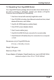
System Management 7.5 Firmware Upgrade Before upgrading your router firmware, you must install the Router Tools. The Firmware Upgrade Utility is included in the tools. The following steps will guide you through the process of upgrade. Note that the examples below use Windows OS. 1. Download the latest firmware from DrayTek's website or FTP site (ftp://ftp.draytek.com/vigor2000/). 2. Use Web Configurator to enable the Firmware Upgrade function.
System Management 3. Click Start -> Programs -> Router Tools -> Firmware Upgrade Utility to launch the Firmware Upgrade Utility. The Router IP field will show the IP address of your router. Click "Browse" to select the new firmware file. The file shown here (v2k00106.bin) is for example purpose only and the latest firmware will have a different file name. Click "Upgrade". The upgrade status will be shown on the progress bar. Note: The definition of firmware filename: v2kxxxxx.
8 Troubleshooting & FAQ 8.1 Using the Telnet Terminal Commands 8.2 Viewing Call Logs 8.3 Viewing ISDN Logs 8.4 Viewing PPP Logs 8.5 Viewing WAN Logs 8.
Troubleshooting & FAQ The following section explains how to use Telnet terminal commands to diagnose your network problems via the built-in debug tool. Our examples use Windows Telnet client software. If you are a Mac user, you should install third-party Telnet client software on your computer. By default, the Linux has a built-in Telnet client. 8.1 Using the Telnet Terminal Commands Click Start -> Run and type "Telnet 192.168.1.1" in the Open box as below.
Troubleshooting & FAQ After assigning a password, type ?. You will see all possible Telnet commands. Command Help: If you are not familiar with these commands, type the command followed by a question mark ?. For example, the ip command is a first level command. Type ip ? to get next level commands as shown below.
Troubleshooting & FAQ Recall Commands: The Telnet terminal also provides a method to recall the command history. Use the Up and Down arrow keys on your keyboard to recall previous commands. Quitting the Telnet Terminal: Enter quit or exit to quit the Telnet terminal. 8.2 Viewing Call Logs The Call log provides a simple method for troubleshooting the call setup or WAN connection problems. By default, the router records WAN connection messages.
Troubleshooting & FAQ 4. Type "log -c" to display the latest call log.
Troubleshooting & FAQ 8.3 Viewing ISDN Logs To capture messages exchanged on the ISDN interface, clear all ISDN logs before you start capturing the new log. The steps are: 1. Login to the Telnet terminal. 2. Type "log -F w" to clear all ISDN logs. 3. Ping to any outside host to trigger the router to dial from your PC. 4. Type "log -i" to display the latest ISDN log. To display all ISDN logs saved in the log buffer, type "log -i -t".
Troubleshooting & FAQ The above example shows detailed D-channel SETUP messages only. Note that all ISDN D-channel messages will be displayed when you type the log -i -t command. To use the command, you will get to know whether the ISDN connection could be established or not. Note that if you cannot read the details, please save these messages in file and attach to support technician. 8.4 Viewing PPP Logs To view PPP logs, type "log -p". The steps are: 1. Login to the Telnet terminal. 2.
Troubleshooting & FAQ The PPP log is useful in solving communication problems for normal ISDN dialup, or PPPoE and PPTP dialup via a DSL modem. 8.5 Viewing WAN Logs To view all WAN logs including ISDN D-channel and PPP/PPPoE/ PPTP messages, the simplest way is to type "log -w -t". The steps are: 1. Login to the Telnet terminal. 2. Type "log -F w" to clear all PPP/PPPoE/PPTP and ISDN logs. 3. Ping to any outside host to trigger the router to dial from your PC. 4.
Troubleshooting & FAQ display all WAN logs, use the "log -w -t" command. 8.6 FAQs The following session cover answers for some frequently asked questions. For more FAQs, please visit DrayTek website (www.draytek.com) or contact your local technical support. 1. What is the default administrator password to login to the router? A: By default, you do not need a password to login to the router. However, for security reason, you should assign a password to protect your router against misusage and hacker attack.
Troubleshooting & FAQ 5. Why can I ping to outside hosts but can not access Internet websites? A: Check if the Primary and the Secondary DNS server have been correctly setup on your PC. Your should have received the DNS server settings from your ISP. If your PC is running a DHCP client, remove any DNS IP address settings. Because the router will assign the DNS settings to the DHCP-client-enabled PC. 6.