Vigor2830 Series User’s Guide ii
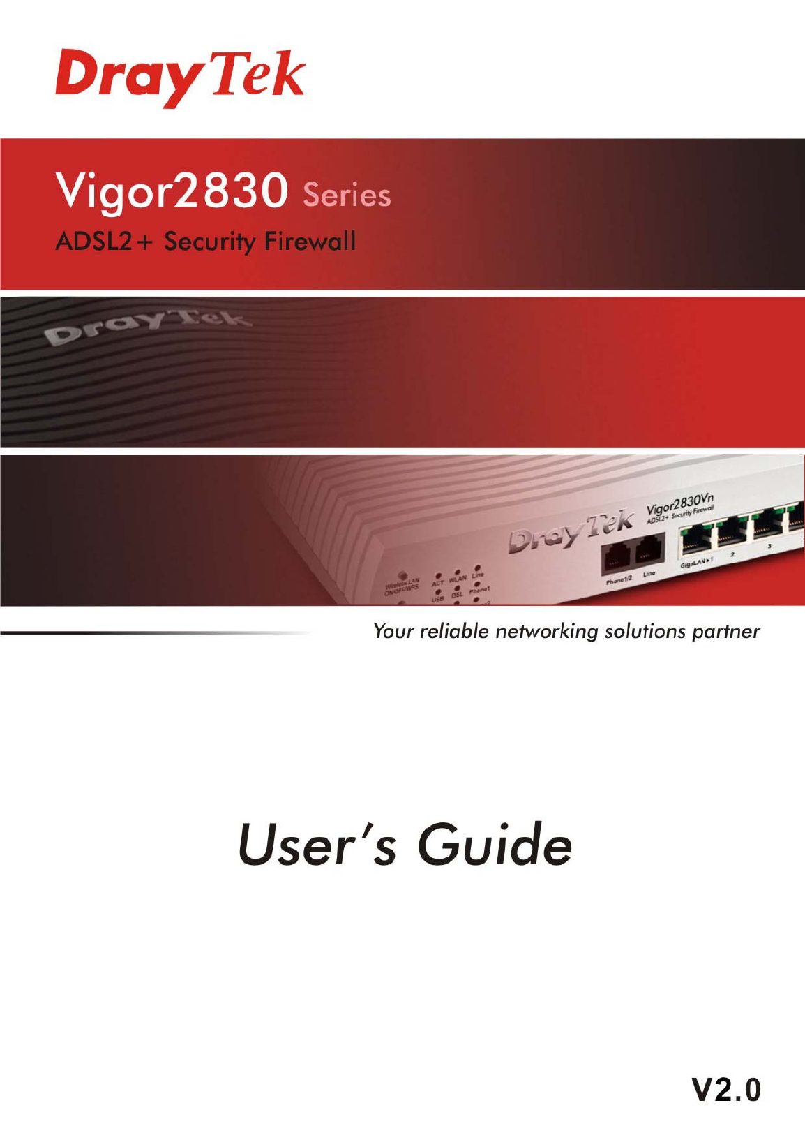
Vigor2830 Series ADSL2+ Security Firewall User’s Guide Version: 2.0 Firmware Version: V3.3.7.
Copyright Information Copyright Declarations Copyright 2012 All rights reserved. This publication contains information that is protected by copyright. No part may be reproduced, transmitted, transcribed, stored in a retrieval system, or translated into any language without written permission from the copyright holders. Trademarks The following trademarks are used in this document: z Microsoft is a registered trademark of Microsoft Corp.
European Community Declarations Manufacturer: Address: Product: DrayTek Corp. No. 26, Fu Shing Road, HuKou Township, HsinChu Industrial Park, Hsin-Chu, Taiwan 303 Vigor2830 Series Router DrayTek Corp. declares that Vigor2830 Series of routers are in compliance with the following essential requirements and other relevant provisions of R&TTE Directive 1999/5/EEC.
Vigor2830 Series User’s Guide vi
Table of Contents Preface ..........................................................................................................1 1.1 Web Configuration Buttons Explanation ................................................................................. 1 1.2 LED Indicators and Connectors .............................................................................................. 2 1.2.1 For Vigor2830 ....................................................................................................
3.3 NAT ....................................................................................................................................... 86 3.3.1 Port Redirection .............................................................................................................. 87 3.3.2 DMZ Host........................................................................................................................ 89 3.3.3 Open Ports..........................................................................
3.11.1 Local Certificate .......................................................................................................... 205 3.11.2 Trusted CA Certificate ................................................................................................ 207 3.11.3 Certificate Backup....................................................................................................... 208 3.12 VoIP.......................................................................................................
Application and Examples.......................................................................287 4.1 How to Configure Multi-Subnet in Vigor2830...................................................................... 287 4.2 How Can I Use FTP to Get the Files from USB Storage Device Connecting to Vigor Router? .................................................................................................................................................. 294 4.3 How to Send out SMS via Vigor Router..........
Preface Vigor2830 series is an ADSL2+ router. It integrates IP layer QoS, NAT session/bandwidth management to help users control works well with large bandwidth. By adopting hardware-based VPN platform and hardware encryption of AES/DES/3DES, the router increases the performance of VPN greatly, and offers several protocols (such as IPSec/PPTP/L2TP) with up to 32 VPN tunnels. The object-based design used in SPI (Stateful Packet Inspection) firewall allows users to set firewall policy with ease.
1.2 LED Indicators and Connectors Before you use the Vigor router, please get acquainted with the LED indicators and connectors first. 1.2.1 For Vigor2830 LED Status Explanation ACT (Activity) CSM Blinking Off On Blinking On WCF On DSL On The router is powered on and running normally. The router is powered off. USB device is connected and ready for use. The data is transmitting.
Interface Description Factory Reset GigaLAN (1-4) DSL WAN2(Giga) USB PWR Restore the default settings. Usage: Turn on the router (ACT LED is blinking). Press the hole and keep for more than 5 seconds. When you see the ACT LED begins to blink rapidly than usual, release the button. Then the router will restart with the factory default configuration. Connecters for local networked devices. Connecter for accessing the Internet through ADSL2/2+. Connecters for remote networked devices.
1.2.2 For Vigor2830n/ Vigor2830n-plus LED Status Explanation ACT (Activity) Blinking Off On Blinking On The router is powered on and running normally. The router is powered off. USB device is connected and ready for use. The data is transmitting. The profile(s) of CSM (Content Security Management) for IM/P2P, URL/Web Content Filter application is enabled from Firewall >>General Setup. (Such profile must be established under CSM menu). Wireless access point is ready.
Interface Description Wireless LAN ON/OFF/WPS GigaLAN (1-4) DSL WAN2(Giga) USB PWR Press "Wireless LAN ON/OFF/WPS" button once to wait for client device making network connection through WPS. Press "Wireless LAN ON/OFF/WPS" button twice to enable (WLAN LED on) or disable (WLAN LED off) wireless connection. Restore the default settings. Usage: Turn on the router (ACT LED is blinking). Press the hole and keep for more than 5 seconds.
1.2.3 For Vigor2830Vn LED Status Explanation ACT (Activity) Blinking Off On Blinking On The router is powered on and running normally. The router is powered off. USB device is connected and ready for use. The data is transmitting. The profile(s) of CSM (Content Security Management) for IM/P2P, URL/Web Content Filter application can be enabled from Firewall >>General Setup. (Such profile must be established under CSM menu). Wireless access point is ready.
Right LED (Green) On Off The port is connected with 1000Mbps. The port is connected with 10/100Mbps when left LED is on.
Interface Description Wireless LAN ON/OFF/WPS Phone 1/2 Line GigaLAN (1-4) DSL WAN2(Giga) USB PWR Press "Wireless LAN ON/OFF/WPS" button once to wait for client device making network connection through WPS. Press "Wireless LAN ON/OFF/WPS" button twice to enable (WLAN LED on) or disable (WLAN LED off) wireless connection. Restore the default settings. Usage: Turn on the router (ACT LED is blinking). Press the hole and keep for more than 5 seconds.
1.3 Hardware Installation Before starting to configure the router, you have to connect your devices correctly. 1. Connect the ADSL interface to the external ADSL splitter with an ADSL line cable for all models. For Vigor2830Vn, also connect Line interface to external ADSL splitter. 2. Connect one end of an Ethernet cable (RJ-45) to one of the LAN ports of the router and the other end of the cable (RJ-45) into the Ethernet port on your computer. 3.
1.4 Printer Installation You can install a printer onto the router for sharing printing. All the PCs connected this router can print documents via the router. The example provided here is made based on Windows XP/2000. For Windows 98/SE/Vista, please visit www.DrayTek.com. Before using it, please follow the steps below to configure settings for connected computers (or wireless clients). 1. Connect the printer with the router through USB/parallel port. 2. Open Start->Settings-> Printer and Faxes. 3.
4. Click Local printer attached to this computer and click Next. 5. In this dialog, choose Create a new port Type of port and use the drop down list to select Standard TCP/IP Port. Click Next.
6. In the following dialog, type 192.168.1.1 (router’s LAN IP) in the field of Printer Name or IP Address and type IP_192.168.1.1 as the port name. Then, click Next. 7. Click Standard and choose Generic Network Card. 8. Then, in the following dialog, click Finish.
9. Now, your system will ask you to choose right name of the printer that you installed onto the router. Such step can make correct driver loaded onto your PC. When you finish the selection, click Next. 10. For the final stage, you need to go back to Control Panel-> Printers and edit the property of the new printer you have added. 11. Select "LPR" on Protocol, type p1 (number 1) as Queue Name. Then click OK. Next please refer to the red rectangle for choosing the correct protocol and LPR name.
The printer can be used for printing now. Most of the printers with different manufacturers are compatible with vigor router. Note 1: Some printers with the fax/scanning or other additional functions are not supported. If you do not know whether your printer is supported or not, please visit www.DrayTek.com to find out the printer list. Open Support >FAQ; find out the link of Printer Server and click it; then click the What types of printers are compatible with Vigor router? link.
Initial Configuration For using the router properly, it is necessary for you to change the password of web configuration for security and adjust primary basic settings. This chapter explains how to setup a password for accessing into the web configurator of Vigor router and how to adjust settings for accessing Internet successfully. 2.1 Accessing Web Page 1. Make sure your PC connects to the router correctly.
4. Now, the Main Screen will appear. Note: The home page will be different slightly in accordance with the type of the router you have. 5. The web page can be logged out according to the chosen condition. The default setting is Auto Logout, which means the web configuration system will logout after 5 minutes without any operation. Change the setting for your necessity. 2.2 Changing Password Please change the password for the original security of the router. 1.
4. Enter the login password (the default is blank) on the field of Old Password. Type New Password. Then click OK to continue. 5. Now, the password has been changed. Next time, use the new password to access the Web Configurator for this router. 2.3 Quick Start Wizard If your router can be under an environment with high speed NAT, the configuration provide here can help you to deploy and use the router quickly. The first screen of Quick Start Wizard is entering login password.
On the next page as shown below, please select the WAN interface that you use. If DSL interface is used, please choose WAN1; if Ethernet interface is used, please choose WAN2; if 3G USB modem is used, please choose WAN3. Then click Next for next step. WAN1, WAN2 and WAN3 will bring up different configuration page. Refer to the following for detailed information. 2.3.1 For WAN1 WAN1 is specified for ADSL connection.
PPPoE is used for most of DSL modem users. All local users can share one PPPoE connection for accessing the Internet. Your service provider will provide you information about user name, password, and authentication mode. 1. Choose WAN1 as WAN Interface and click the Next button; you will get the following page. Available settings are explained as follows: Item Description VPI Type in the value provided by ISP.
2. Back Click it to return to previous setting page. Next Click it to get into the next setting page. Cancel Click it to give up the quick start wizard. After finished the above settings, simply click Next. Available settings are explained as follows: 3. Item Description User Name Type in the valid user name (maximum 63 characters) provided by the ISP in this field. Password Type a valid password provided by the ISP. Confirm Password Retype the password.
4. Click Finish. A page of Quick Start Wizard Setup OK!!! will appear. Then, the system status of this protocol will be shown. 5. Now, you can enjoy surfing on the Internet. 1483 Bridged IP /1483 Routed IP 1. Choose WAN1 as WAN Interface and click the Next button; you will get the following page. Available settings are explained as follows: Item Description VPI Type in the value provided by ISP.
Cancel Click it to give up the quick start wizard. 2. Please type in the IP address/mask/gateway information originally provided by your ISP. Then click Next for viewing summary of such connection. 3. Click Finish. A page of Quick Start Wizard Setup OK!!! will appear. Then, the system status of this protocol will be shown. 4. Now, you can enjoy surfing on the Internet.
2.3.2 For WAN2 (Ethernet) WAN2 is dedicated to physical mode in Ethernet. If you choose WAN2, please specify physical type. Then, click Next. On the next page as shown below, please select the appropriate Internet access type according to the information from your ISP. For example, you should select PPPoE mode if the ISP provides you PPPoE interface. Then click Next for next step. PPPoE PPPoE stands for Point-to-Point Protocol over Ethernet. It relies on two widely accepted standards: PPP and Ethernet.
1. Choose WAN2 as the WAN Interface and click the Next button. The following page will be open for you to specify Internet Access Type. 2. Click PPPoE as the Internet Access Type. Then click Next to continue. Available settings are explained as follows: Item Description User Name Type in the valid user name (maximum 63 characters) provided by the ISP in this field. Password Type a valid password provided by the ISP. Confirm Password Retype the password.
3. Please manually enter the Username/Password provided by your ISP. Click Next for viewing summary of such connection. 4. Click Finish. A page of Quick Start Wizard Setup OK!!! will appear. Then, the system status of this protocol will be shown. 5. Now, you can enjoy surfing on the Internet. PPTP/L2TP 1. Choose WAN2 as the WAN Interface and click the Next button. The following page will be open for you to specify Internet Access Type.
2. Click PPTP/L2TP as the Internet Access Type. Then click Next to continue. Available settings are explained as follows: 3. Item Description User Name Assign a specific valid user name provided by the ISP. Password Assign a valid password provided by the ISP. Confirm Password Retype the password. WAN IP Configuration Obtain an IP address automatically – the router will get an IP address automatically from DHCP server. Specify an IP address – you have to type relational settings manually.
4. Click Finish. A page of Quick Start Wizard Setup OK!!! will appear. Then, the system status of this protocol will be shown. 5. Now, you can enjoy surfing on the Internet. Static IP 1. Choose WAN2 as the WAN Interface and click the Next button. The following page will be open for you to specify Internet Access Type. 2. Click Static IP as the Internet Access type. Simply click Next to continue.
Available settings are explained as follows: 3. Item Description WAN IP Type the IP address. Subnet Mask Type the subnet mask. Gateway Type the IP address of gateway. Primary DNS Type in the primary IP address for the router. Secondary DNS Type in secondary IP address for necessity in the future. Back Click it to return to previous setting page. Next Click it to get into the next setting page. Cancel Click it to give up the quick start wizard.
4. Click Finish. A page of Quick Start Wizard Setup OK!!! will appear. Then, the system status of this protocol will be shown. 5. Now, you can enjoy surfing on the Internet.
DHCP 1. Choose WAN2 as WAN Interface and click the Next button. The following page will be open for you to specify Internet Access Type. 2. Click DHCP as the Internet Access type. Simply click Next to continue. Available settings are explained as follows: ed as follows: Item Description Host Name Type the name of the host. MAC Some Cable service providers specify a specific MAC address for access authentication. In such cases you need to enter the MAC address.
Next Click it to get into the next setting page. Cancel Click it to give up the quick start wizard. 3. After finished the settings above, click Next for viewing summary of such connection. 4. Click Finish. A page of Quick Start Wizard Setup OK!!! will appear. Then, the system status of this protocol will be shown. 5. Now, you can enjoy surfing on the Internet.
2.3.3 For WAN3 (USB) To use 3G USB modem for network connection, please choose WAN3. 1. Choose WAN3 as WAN Interface. 2. Then, click Next for viewing summary of such connection. 3. Click Finish. A page of Quick Start Wizard Setup OK!!! will appear. Then, the system status of this protocol will be shown. 4. Now, you can enjoy surfing on the Internet.
2.4 Service Activation Wizard Service Activation Wizard can guide you to activate WCF service (Web Content Filter) with a quick and easy way. For the Service Activation Wizard is only available for admin operation, therefore, please type “admin/admin” on Username/Password while Logging into the web configurator. Service Activation Wizard is a tool which allows you to use trial version or update the license of WCF directly without accessing into the server (MyVigor) located on http://myvigor.draytek.com.
3. In the following page, you can activate the Web content filter services at the same time or individually. When you finish the selection, please click Next. Commtouch is the web content filter based on Commtouch operated in the worldwide. There is a 30-day trial period. After trial, you can purchase DrayTek's prepared Commtouch GlobalView WCF package from retailing outlets. 4. Setting confirmation page will be displayed as follows, please click Next. 5.
Note: The service will be activated and applied as the default rule configured in Firewall>>General Setup. 6. Now, the web page will display the service that you have activated according to your selection(s). The valid time for the free trial of these services is one month. Later, if you need to extend the license valid time for the same service, you can also use the Service Activation Wizard again to reach your goal by clicking the radio button of Formal edition with license key and clicking Next.
2.5 Online Status 2.5.1 Physical Connection Such page displays the physical connection status such as LAN connection status, WAN connection status, ADSL information, and so on. If you select PPPoE as the protocol, you will find out a link of Dial PPPoE or Drop PPPoE in the Online Status web page. Detailed explanation is shown below: Item Description LAN Status Primary DNS-Displays the primary DNS server address for WAN interface.
Item Status Description not enabled. Yes in green means such interface is enabled. Line – Displays the physical connection (VDSL, ADSL, Ethernet, or USB) of this interface. Name – Display the name of the router. Mode - Displays the type of WAN connection (e.g., PPPoE). Up Time - Displays the total uptime of the interface. IP - Displays the IP address of the WAN interface. GW IP - Displays the IP address of the default gateway. TX Packets - Displays the total transmitted packets at the WAN interface.
2.6 Saving Configuration Each time you click OK on the web page for saving the configuration, you can find messages showing the system interaction with you. Ready indicates the system is ready for you to input settings. Settings Saved means your settings are saved once you click Finish or OK button. 2.7 Registering Vigor Router You have finished the configuration of Quick Start Wizard and you can surf the Internet at any time.
3 A Login page will be shown on the screen. Please type the account and password that you created previously. And click Login. If not, please refer to section 4.12 Creating an Account for MyVigor. 4 The following page will be displayed after you logging in MyVigor. From this page, please click Add or Product Registration.
5 When the following page appears, please type in Nickname (for the router) and choose the right registration date from the popup calendar (it appears when you click on the box of Registration Date). After adding the basic information for the router, please click Submit. 6 When the following page appears, your router information has been added to the database. 7 Now, you have finished the product registration. 8 After clicking OK, you will see the following page.
Advanced Configuration This chapter will guide users to execute advanced web configuration. 1. Open a web browser on your PC and type http://192.168.1.1. The window will ask for typing username and password. 2. Please type “admin/admin” on Username/Password for administration operation. Now, the Main Screen will appear. Note that different model will have different web pages. 3.1 WAN Quick Start Wizard offers user an easy method to quick setup the connection mode for the router.
As the router plays a role to manage and further protect its LAN, it interconnects groups of host PCs. Each of them has a private IP address assigned by the built-in DHCP server of the Vigor router. The router itself will also use the default private IP address: 192.168.1.1 to communicate with the local hosts. Meanwhile, Vigor router will communicate with other network devices through a public IP address.
3.1.2 General Setup This section will introduce some general settings of Internet and explain the connection modes for WAN1, WAN2 and WAN3 in details. This router supports multiple-WAN function. It allows users to access Internet and combine the bandwidth of the multiple WANs to speed up the transmission through the network. Each WAN port can connect to different ISPs, Even if the ISPs use different technology to provide telecommunication service (such as DSL, Cable modem, etc.).
Active Mode Display whether such WAN interface is Active device or backup device. Backup WAN Display the Backup WAN interface for such WAN when it is disabled. Note: In default, each WAN port is enabled. WAN1 with ADSL WAN1 is fixed with physical mode of ADSL. Detailed explanation is shown below: Item Description Enable Choose Yes to invoke the settings for this WAN interface. Choose No to disable the settings for this WAN interface. Display Name Type the description for such WAN interface.
VLAN Tag insertion Enable – Enable the function of VLAN with tag. The router will add specific VLAN number to all packets on the WAN while sending them out. Please type the tag value and specify the priority for the packets sending by WAN1. Disable – Disable the function of VLAN with tag. Tag value – Type the value as the VLAN ID number. The range is form 0 to 4095. Priority – Type the packet priority number for such VLAN. The range is from 0 to 7.
WAN2 with Ethernet WAN2 is fixed with physical mode of Ethernet. Detailed explanation is shown below: Item Description Enable Choose Yes to invoke the settings for this WAN interface. Choose No to disable the settings for this WAN interface. Display Name Type the description for such WAN interface. Physical Mode Display the physical mode of such WAN interface. Physical type You can change the physical type for WAN2 or choose Auto negotiation for determined by the system.
VLAN Tag insertion Enable – Enable the function of VLAN with tag. The router will add specific VLAN number to all packets on the WAN while sending them out. Please type the tag value and specify the priority for the packets sending by WAN1. Disable – Disable the function of VLAN with tag. Tag value – Type the value as the VLAN ID number. The range is form 0 to 4095. Priority – Type the packet priority number for such VLAN. The range is from 0 to 7.
WAN3 with USB To use 3G network connection through 3G USB Modem, please configure WAN3 interface. Detailed explanation is shown below: Item Description Enable Choose Yes to invoke the settings for this WAN interface. Choose No to disable the settings for this WAN interface. Display Name Type the description for such WAN interface. Physical Mode Display the physical mode of such WAN interface. Physical type In such WAN interface, no type can be selected.
Backup WAN If you choose Backup as the Active Mode, Backup WAN will be changed into Backup Type. You have to specify which role the WAN interface should play if you want to backup multiple WANs. However, ignore this setting if you want to backup a single WAN. When any of selected WAN disconnect – Such backup WAN will be activated when any master WAN interface disconnects. When all of selected WAN disconnect – Such backup WAN will be activated only when all master WAN interfaces disconnect. 3.1.
Detailed explanation is shown below: Item Description Index Display the WAN interface. Display Name It shows the name of the WAN1/WAN2/WAN3 that entered in general setup. Physical Mode It shows the physical connection for WAN1(ADSL)/WAN2 (Ethernet) /WAN3 (3G USB Modem) according to the real network connection. Access Mode Use the drop down list to choose a proper access mode. The details page of that mode will be popped up.
Details Page for PPPoE/PPPoA in WAN1 To choose PPPoE /PPPoA as the accessing protocol of the Internet, please select PPPoE/PPPoA from the WAN>>Internet Access >>WAN1 page. The following web page will be shown. Detailed explanation is shown below: Item Description Enable/Disable Click Enable for activating this function. If you click Disable, this function will be closed and all the settings that you adjusted in this page will be invalid.
protocol, then it is not necessary for you to change any settings in this group. Modulation –Default setting is Multimode. Choose the one that fits the requirement of your router. PPPoE Pass-through The router offers PPPoE dial-up connection. Besides, you also can establish the PPPoE connection directly from local clients to your ISP via the Vigor router. When PPPoA protocol is selected, the PPPoE package transmitted by PC will be transformed into PPPoA package and sent to WAN server.
PPP Authentication – Select PAP only or PAP or CHAP for PPP. If you want to connect to Internet all the time, you can check Always On. Idle Timeout – Set the timeout for breaking down the Internet after passing through the time without any action. IP Address Assignment Method (IPCP) Usually ISP dynamically assigns IP address to you each time you connect to it and request. In some case, your ISP provides service to always assign you the same IP address whenever you request.
Details Page for MPoA in WAN1 MPoA is a specification that enables ATM services to be integrated with existing LANs, which use either Ethernet, token-ring or TCP/IP protocols. The goal of MPoA is to allow different LANs to send packets to each other via an ATM backbone. To use MPoA as the accessing protocol of the Internet, select MPoA from the WAN>>Internet Access >>WAN1 page. The following web page will appear.
that fits the requirement of your router. WAN Connection Detection Such function allows you to verify whether network connection is alive or not through ARP Detect or Ping Detect. Mode – Choose ARP Detect or Ping Detect for the system to execute for WAN detection. Ping IP – If you choose Ping Detect as detection mode, you have to type IP address in this field for pinging. TTL (Time to Live) – Displays value for your reference. TTL value is set by telnet command.
Obtain an IP address automatically – Click this button to obtain the IP address automatically. Router Name – Type in the router name provided by ISP. Domain Name – Type in the domain name that you have assigned. Specify an IP address – Click this radio button to specify some data. IP Address – Type in the private IP address. Subnet Mask – Type in the subnet mask. Gateway IP Address – Type in gateway IP address. Default MAC Address – Type in MAC address for the router.
ISP Access Setup Enter your allocated username, password and authentication parameters according to the information provided by your ISP. Username – Type in the valid user name (maximum 63 characters) provided by the ISP in this field. Password – Type in the password provided by ISP in this field. Index (1-15) in Schedule Setup - You can type in four sets of time schedule for your request.
Fixed IP – Click Yes to use this function and type in a fixed IP address in the box of Fixed IP Address. Default MAC Address – You can use Default MAC Address or specify another MAC address by typing on the boxes of MAC Address for the router. Specify a MAC Address – Type the MAC address for the router manually. After finishing all the settings here, please click OK to activate them.
Detailed explanation is shown below: Item Description Enable / Disable Click Enable for activating this function. If you click Disable, this function will be closed and all the settings that you adjusted in this page will be invalid. Keep WAN Connection Normally, this function is designed for Dynamic IP environments because some ISPs will drop connections if there is no traffic within certain periods of time. Check Enable PING to keep alive box to activate this function.
RIP(RFC1058) specifying how routers exchange routing tables information. Click Enable RIP for activating this function. WAN IP Network Settings This group allows you to obtain an IP address automatically and allows you type in IP address manually. WAN IP Alias - If you have multiple public IP addresses and would like to utilize them on the WAN interface, please use WAN IP Alias. You can set up to 8 public IP addresses other than the current one you are using.
Detailed explanation is shown below: Item Description PPTP/L2TP Enable PPTP- Click this radio button to enable a PPTP client to establish a tunnel to a DSL modem on the WAN interface. Enable L2TP - Click this radio button to enable a L2TP client to establish a tunnel to a DSL modem on the WAN interface. Disable – Click this radio button to close the connection through PPTP or L2TP. Server Address - Specify the IP address of the PPTP/L2TP server if you enable PPTP/L2TP client mode.
other than the current one you are using. Fixed IP - Usually ISP dynamically assigns IP address to you each time you connect to it and request. In some case, your ISP provides service to always assign you the same IP address whenever you request. In this case, you can fill in this IP address in the Fixed IP field. Please contact your ISP before you want to use this function. Click Yes to use this function and type in a fixed IP address in the box. Fixed IP Address -Type a fixed IP address.
Details Page for PPP in WAN3 To use PPP (for 3G USB Modem) as the accessing protocol of the internet, please choose Internet Access from WAN menu. Then, select PPP mode for WAN2. The following web page will be shown. Detailed explanation is shown below: Item Description 3G Modem Enable / Disable - Click Enable for activating this function. If you click Disable, this function will be closed and all the settings that you adjusted in this page will be invalid.
PPP Username - Type the PPP username (optional). PPP Password - Type the PPP password (optional). PPP Authentication - Select PAP only or PAP or CHAP for PPP. Index (1-15) in Schedule Setup - You can type in four sets of time schedule for your request.
you enabled here will be shown in the Multi-PVC channel drop down list on the web page of Internet Access. Though you can enable eight channels in this page, yet only one channel can be chosen on the web page of Internet Access. VPI Type in the value provided by your ISP. VCI Type in the value provided by your ISP. QoS Type Select a proper QoS type for the channel. Protocol Select a proper protocol for this channel. Encapsulation Choose a proper type for this channel.
Available settings are explained as follows: Item Description WAN for Router-borne Application Choose the router service for channel 5, 6 or 7. Management - It can be specified for general management (Web configuration/telnet/TR069). If you choose Management, the configuration for this PVC will be effective for Web configuration/telnet/TR069. VoIP - It can be specified for VoIP only. If you choose VoIP, the configuration for this PVC will be effective for VoIP data transmitting and receiving.
ATM QoS Such configuration is applied to upstream packets. Such information will be provided by ISP. Please contact with your ISP for detailed information. Available settings are explained as follows: Item Description QoS Type Select a proper QoS type for the channel according to the information that your ISP provides. PCR It represents Peak Cell Rate. The default setting is “0”. SCR It represents Sustainable Cell Rate. The value of SCR must be smaller than PCR.
Port-based Bridge General page lets you set the first PVC. As to set the second PVC line, please click the Port-based Bridge tab to open Bridge configuration page. Available settings are explained as follows: Item Description Enable Check this box to enable that channel. Only channel 3 to 8 can be set in this page, for channel 1 to 2 are reserved for NAT using. P1 to P4 It means the LAN port 1 to 4. Check the box to designate the LAN port for channel 3 to 8.
3.1.5 Load-Balance Policy This router supports the function of load balancing. It can assign traffic with protocol type, IP address for specific host, a subnet of hosts, and port range to be allocated in WAN1, WAN2, and WAN3 interface. The user can assign traffic category and force it to go to dedicate network interface based on the following web page setup. Twenty policies of load-balance are supported by this router. Note: Load-Balance Policy is running only when WAN1, WAN2 and WAN3 are activated.
Click Index 1 to access into the following page for configuring load-balance policy. Available settings are explained as follows: Item Description Enable Check this box to enable this policy. Protocol Use the drop-down menu to choose a proper protocol for the WAN interface. Binding WAN interface Choose the WAN interface (WAN1/WAN2/WAN3) for binding. Auto failover to other WAN – Check this button to lead the data passing through other WAN automatically when the selected WAN interface is failover.
3.2 LAN Local Area Network (LAN) is a group of subnets regulated and ruled by router. The design of network structure is related to what type of public IP addresses coming from your ISP. 3.2.1 Basics of LAN The most generic function of Vigor router is NAT. It creates a private subnet of your own. As mentioned previously, the router will talk to other public hosts on the Internet by using public IP address and talking to local hosts by using its private IP address.
What is Routing Information Protocol (RIP) Vigor router will exchange routing information with neighboring routers using the RIP to accomplish IP routing. This allows users to change the information of the router such as IP address and the routers will automatically inform for each other. What is Static Route When you have several subnets in your LAN, sometimes a more effective and quicker way for connection is the Static routes function rather than other method.
3.2.2 General Setup This page provides you the general settings for LAN. Click LAN to open the LAN settings page and choose General Setup. There are four subnets provided by the router which allow users to divide groups into different subnets (LAN1 – LAN4). In addition, different subnets can link for each other by configuring Inter-LAN Routing. At present, LAN1 setting is fixed with NAT mode only. LAN2 – LAN4 can be operated under NAT or Route mode. IP Routed Subnet can be operated under Route mode.
Details Page for LAN1 Available settings are explained as follows: Item Description IP Address Type in private IP address for connecting to a local private network (Default: 192.168.1.1). Subnet Mask Type in an address code that determines the size of the network. (Default: 255.255.255.0/ 24) RIP Protocol Control Disable - deactivate the RIP protocol. It will lead to a stoppage of the exchange of routing information between routers. (Default) Enable – activate the RIP protocol.
the DHCP server to start with when issuing IP addresses. If the 1st IP address of your router is 192.168.1.1, the starting IP address must be 192.168.1.2 or greater, but smaller than 192.168.1.254. IP Pool Counts - Enter the maximum number of PCs that you want the DHCP server to assign IP addresses to. The default is 50 and the maximum is 253. Gateway IP Address - Enter a value of the gateway IP address for the DHCP server.
Details Page for LAN2/LAN3/LAN4 Available settings are explained as follows: Item Description Network Configuration Enable/Disable - Click Enable to enable such configuration. Click Disable to disable such configuration. For NAT Usage - Click this radio button to invoke NAT function. For Routing Usage - Click this radio button to invoke this function. IP Address - Type in private IP address for connecting to a local private network (Default: 192.168.1.1).
default is 50 and the maximum is 253. Gateway IP Address - Enter a value of the gateway IP address for the DHCP server. The value is usually as same as the 1st IP address of the router, which means the router is the default gateway. Details Page for IP Routed Subnet Available settings are explained as follows: Item Description Network Configuration Enable/Disable - Click Enable to enable such configuration. Click Disable to disable such configuration.
If you want to use another DHCP server in the network other than the Vigor Router’s, you can let Relay Agent help you to redirect the DHCP request to the specified location. Start IP Address - Enter a value of the IP address pool for the DHCP server to start with when issuing IP addresses. If the 1st IP address of your router is 192.168.1.1, the starting IP address must be 192.168.1.2 or greater, but smaller than 192.168.1.254.
Item Description Set to Factory Default Click it to return to factory default settings. Viewing Routing Table Displays the routing table for your reference. Index The number (1 to 10) under Index allows you to open next page to set up static route. Destination Address Displays the destination address of the static route. Status Displays the status of the static route.
1. Go to LAN page and click General Setup, select 1st Subnet as the RIP Protocol Control. Then click the OK button. Note: There are two reasons that we have to apply RIP Protocol Control on 1st Subnet. The first is that the LAN interface can exchange RIP packets with the neighboring routers via the 1st subnet (192.168.1.0/24). The second is that those hosts on the internal private subnets (ex. 192.168.10.
4. Go to Diagnostics and choose Routing Table to verify current routing table.
3.2.4 VLAN (Multi-Subnet) Virtual LAN function provides you a very convenient way to manage hosts by grouping them based on the physical port. Go to LAN page and select VLAN. The following page will appear. Click Enable to invoke VLAN function. The multi-subnet can let a small businesses have much better isolation for multi-occupancy applications. Tagged VLAN The tagged VLANs (802.1q) can also mark data with a VLAN identifier.
Subnet Choose one of them to make the selected VLAN mapping to the specified subnet only. For example, LAN1 is specified for VLAN0. It means that PCs grouped under VLAN0 can get the IP address(es) that specified by the subnet. VLAN Tag Enable – Check it to enable the function of VLAN with tag. The router will add specific VLAN number to all packets on the LAN while sending them out. Please type the tag value and specify the priority for the packets sending by LAN.
3.2.5 Bind IP to MAC This function is used to bind the IP and MAC address in LAN to have a strengthening control in network. When this function is enabled, all the assigned IP and MAC address binding together cannot be changed. If you modified the binding IP or MAC address, it might cause you not access into the Internet. Click LAN and click Bind IP to MAC to open the setup page. Available settings are explained as follows: Item Description Enable Click this radio button to invoke this function.
Refresh Refresh the ARP table listed below to obtain the newest ARP table information. IP Bind List It displays a list for the IP bind to MAC information. Add and Edit IP Address – Type the IP address that will be used for the specified MAC address. Mac Address – Type the MAC address that is used to bind with the assigned IP address. Comment – Type a brief description for the entry. Show Comment – Check it to display the content of the comment.
Item Description Port Mirror Check Enable to activate this function. Or, check Disable to close this function. Mirror Port Select a port to view traffic sent from mirrored ports. Mirrored port Select which ports are necessary to be mirrored. After finishing all the settings here, please click OK to save the configuration. 3.3 NAT Usually, the router serves as an NAT (Network Address Translation) router. NAT is a mechanism that one or more private IP addresses can be mapped into a single public one.
3.3.1 Port Redirection Port Redirection is usually set up for server related service inside the local network (LAN), such as web servers, FTP servers, E-mail servers etc. Most of the case, you need a public IP address for each server and this public IP address/domain name are recognized by all users.
Available settings are explained as follows: Item Description Enable Check this box to enable such port redirection setting. Mode Two options (Single and Range) are provided here for you to choose. To set a range for the specific service, select Range. In Range mode, if the public port (start port and end port) and the starting IP of private IP had been entered, the system will calculate and display the ending IP of private IP automatically.
Note that the router has its own built-in services (servers) such as Telnet, HTTP and FTP etc. Since the common port numbers of these services (servers) are all the same, you may need to reset the router in order to avoid confliction. For example, the built-in web configurator in the router is with default port 80, which may conflict with the web server in the local network, http://192.168.1.13:80.
The security properties of NAT are somewhat bypassed if you set up DMZ host. We suggest you to add additional filter rules or a secondary firewall. Click DMZ Host to open the following page: DMZ Host for WAN2 and WAN3 is slightly different with WAN1. Active True IP selection is available for WAN1 only. See the following figure.
If you previously have set up WAN Alias for PPPoE or Static or Dynamic IP mode in WAN2 interface, you will find them in Aux. WAN IP for your selection. Available settings are explained as follows: Item Description Enable Check to enable the DMZ Host function. Private IP Enter the private IP address of the DMZ host, or click Choose PC to select one. Choose PC Click this button and then a window will automatically pop up, as depicted below.
3.3.3 Open Ports Open Ports allows you to open a range of ports for the traffic of special applications. Common application of Open Ports includes P2P application (e.g., BT, KaZaA, Gnutella, WinMX, eMule and others), Internet Camera etc. Ensure that you keep the application involved up-to-date to avoid falling victim to any security exploits.
Available settings are explained as follows: Item Description Enable Open Ports Check to enable this entry. Comment Make a name for the defined network application/service. WAN IP Specify the WAN IP address that will be used for this entry. This setting is available when WAN IP Alias is configured. Local Computer Enter the private IP address of the local host or click Choose PC to select one.
Available settings are explained as follows: Item Description Protocol Display the protocol used for this address mapping. Public IP Display the public IP address selected for this entry, e.g., 172.16.3.102. Private IP Display the private IP set for this address mapping, e.g., 192.168.1.10. Mask Display the subnet mask selected for this address mapping. Status Display the status for the entry, enable or disable. Click the index number link to open the configuration page.
WAN Interface Choose the WAN interface for such address mapping profile. WAN IP Select an IP address (the selections provided here are set in IP Alias List of Network >>WAN interface). Local host can use this IP to connect to Internet. If you want to choose any one of the Public IP settings, you must specify some IP addresses in the IP Alias List of the Static/DHCP Configuration page first. If you did not type in any IP address in the IP Alias List, the Public IP setting will be empty in this field.
Triggering Port Display the port of the triggering packets. Incoming Protocol Display the protocol for the incoming data of such triggering profile. Incoming Port Display the port for the incoming data of such triggering profile. Status Display if the rule is active or de-active. Click the index number link to open the configuration page. Available settings are explained as follows: Item Description Enable Check to enable this entry.
Triggering Port Type the port or port range for such trigger profile. Incoming Protocol When the triggering packets received, it is expected the incoming packets will use the selected protocol. Select the protocol (TCP, UDP or TCP/UDP) for the incoming data of such triggering profile. Incoming Port Type the port or port range for the incoming packets.
3.4 Firewall 3.4.1 Basics for Firewall While the broadband users demand more bandwidth for multimedia, interactive applications, or distance learning, security has been always the most concerned. The firewall of the Vigor router helps to protect your local network against attack from unauthorized outsiders. It also restricts users in the local network from accessing the Internet. Furthermore, it can filter out specific packets that trigger the router to build an unwanted outgoing connection.
Stateful Packet Inspection (SPI) Stateful inspection is a firewall architecture that works at the network layer. Unlike legacy static packet filtering, which examines a packet based on the information in its header, stateful inspection builds up a state machine to track each connection traversing all interfaces of the firewall and makes sure they are valid. The stateful firewall of Vigor router not just examine the header information also monitor the state of the connection.
3.4.2 General Setup General Setup allows you to adjust settings of IP Filter and common options. Here you can enable or disable the Call Filter or Data Filter. Under some circumstance, your filter set can be linked to work in a serial manner. So here you assign the Start Filter Set only. Also you can configure the Log Flag settings, Apply IP filter to VPN incoming packets, and Accept incoming fragmented UDP packets. Click Firewall and click General Setup to open the general setup page.
will be filtered by firewall settings configured by Vigor router if such feature is enabled. If the firewall system does not have any response (pass or block) for these packets, such as no response coming from web content filter, then the router’s firewall will block the packets directly. Default Rule Page Such page allows you to choose filtering profiles including QoS, Load-Balance policy, WCF, APP Enforcement, URL Content Filter, AI/AV, AS, for data transmission via Vigor router.
Load-Balance Policy Choose the WAN interface for applying Load-Balance Policy. User Management Such item is available only when Rule-Based is selected in User Management>>General Setup. The general firewall rule will be applied to the user/user group/all users specified here. Note: When there is no user profile or group profile existed, Create New User or Create New Group item will appear for you to click to create a new one.
CSM>> Web Content Filter web page first. Or choose [Create New] from the drop down list in this page to create a new profile. For troubleshooting needs, you can specify to record information for Web Content Filter by checking the Log box. It will be sent to Syslog server. Please refer to section Syslog/Mail Alert for more detailed information. Advance Setting Click Edit to open the following window. However, it is strongly recommended to use the default settings here.
3.4.3 Filter Setup Click Firewall and click Filter Setup to open the setup page. To edit or add a filter, click on the set number to edit the individual set. The following page will be shown. Each filter set contains up to 7 rules. Click on the rule number button to edit each rule. Check Active to enable the rule. Available settings are explained as follows: Item Description Filter Rule Click a button numbered (1 ~ 7) to edit the filter rule. Click the button will open Edit Filter Rule web page.
To edit Filter Rule, click the Filter Rule index button to enter the Filter Rule setup page. Available settings are explained as follows: Item Description Check to enable the Filter Rule Check this box to enable the filter rule. Comments Enter filter set comments/description. Maximum length is 14- character long. Index(1-15) Set PCs on LAN to work at certain time interval only. You may choose up to 4 schedules out of the 15 schedules pre-defined in Applications >> Schedule setup.
LAN. Source/Destination IP Click Edit to access into the following dialog to choose the source/destination IP or IP ranges. To set the IP address manually, please choose Any Address/Single Address/Range Address/Subnet Address as the Address Type and type them in this dialog. In addition, if you want to use the IP range from defined groups or objects, please choose Group and Objects as the Address Type. From the IP Group drop down list, choose the one that you want to apply.
Service Type. Protocol - Specify the protocol(s) which this filter rule will apply to. Source/Destination Port – (=) – when the first and last value are the same, it indicates one port; when the first and last values are different, it indicates a range for the port and available for this service type.
MAC Bind IP Strict –Make the MAC address and IP address settings configured in IP Object for Source IP and Destination IP be bound for applying such filter rule. No-Strict - no limitation. Quality of Service Choose one of the QoS rules to be applied as firewall rule. For detailed information of setting QoS, please refer to the related section later. Load-Balance policy Choose the WAN interface for applying Load-Balance Policy.
Web Content Filter Select one of the Web Content Filter profile settings (created in CSM>> Web Content Filter) for applying with this router. Please set at least one profile for anti-virus in CSM>> Web Content Filter web page first. Or choose [Create New] from the drop down list in this page to create a new profile. For troubleshooting needs, you can specify to record information for Web Content Filter by checking the Log box. It will be sent to Syslog server.
Window size – It determines the size of TCP protocol (0~65535). The more the value is, the better the performance will be. However, if the network is not stable, small value will be proper. Session timeout–Setting timeout for sessions can make the best utilization of network resources. However, Queue timeout is configured for TCP protocol only; session timeout is configured for the data flow which matched with the firewall rule.
111 Vigor2830 Series User’s Guide
3.4.4 DoS Defense As a sub-functionality of IP Filter/Firewall, there are 15 types of detect/ defense function in the DoS Defense setup. The DoS Defense functionality is disabled for default. Click Firewall and click DoS Defense to open the setup page. Available settings are explained as follows: Item Description Enable Dos Defense Check the box to activate the DoS Defense Functionality. Select All Click this button to select all the items listed below.
Enable ICMP flood defense Check the box to activate the ICMP flood defense function. Similar to the UDP flood defense function, once if the Threshold of ICMP packets from Internet has exceeded the defined value, the router will discard the ICMP echo requests coming from the Internet. The default setting for threshold and timeout are 50 packets per second and 10 seconds, respectively.
Many machines may crash when receiving ICMP datagrams (packets) that exceed the maximum length. To avoid this type of attack, the Vigor router is designed to be capable of discarding any fragmented ICMP packets with a length greater than 1024 octets. Block Ping of Death Check the box to activate the Block Ping of Death function. This attack involves the perpetrator sending overlapping packets to the target hosts so that those target hosts will hang once they re-construct the packets.
3.5 User Management User Management is a security feature which disallows any IP traffic (except DHCP-related packets) from a particular host until that host has correctly supplied a valid username and password. Instead of managing with IP address/MAC address, User Management function manages hosts with user account. Network administrator can give different firewall policies or rules for different hosts with different User Management accounts. This is more flexible and convenient for network management.
3.5.1 General Setup General Setup can determine the standard (rule-based or user-based) for the users controlled by User Management. The mode (standard) selected here will influence the contents of the filter rule(s) applied to every user. Available settings are explained as follows: Item Description Mode There are two modes offered here for you to choose. Each mode will bring different filtering effect to the users involved.
3.5.2 User Profile This page allows you to set customized profiles (up to 200) which will be applied for users controlled under User Management. Simply open User Management>>User Profile. To set the user profile, please click any index number link to open the following page. Notice that profile 1 (admin) and profile 2 (System Reservation) are factory default settings. Profile 2 is reserved for future use.
Available settings are explained as follows: Item Description Enable this account Check this box to enable such user profile. User Name Type a name for such user profile (e.g., LAN_User_Group_1, WLAN_User_Group_A, WLAN_User_Group_B, etc). When a user tries to access Internet through this router, an authentication step must be performed first. The user has to type the User Name specified here to pass the authentication. When the user passes the authentication, he/she can access Internet via this router.
For the detailed configuration, simply refer to Firewall>>Filter Rule. The firewall filter rules that are not selected in Firewall>>General>>Default rule can be available for use in User Management>>User Profile. External Service Authentication The router will authenticate the dial-in user by itself or by external service such as LDAP server or Radius server. If LDAP or Radius is selected here, it is not necessary to configure the password setting above.
window with remaining time of connection for such user will be displayed. Next, the user can access Internet through any browser on Windows. Note that Alert Tool can be downloaded from DrayTek web site. Telnet – If it is selected, the user can use Telnet command to perform the authentication job.
Available settings are explained as follows: Item Description Name Type a name for this user group. Available User Objects You can gather user profiles (objects) from User Profile page within one user group. All the available user objects that you have created will be shown in this box. Notice that user object, Admin and Dial-In User are factory settings. User defined profiles will be numbered with 3, 4, 5 and so on. Selected Keyword Objects Click box.
Available settings are explained as follows: Item Description Refresh Seconds Use the drop down list to choose the time interval of refreshing data flow that will be done by the system automatically. Refresh Click this link to refresh this page manually. Index Display the number of the data flow. Active User Display the users which connect to Vigor router currently. You can click the link under the username to open the user profile setting page for that user.
3.6 Objects Settings For IPs in a range and service ports in a limited range usually will be applied in configuring router’s settings, therefore we can define them with objects and bind them with groups for using conveniently. Later, we can select that object/group that can apply it. For example, all the IPs in the same department can be defined with an IP object (a range of IP address). 3.6.1 IP Object You can set up to 192 sets of IP Objects with different conditions.
Click the number under Index column for settings in detail. Available settings are explained as follows: Item Description Name Type a name for this profile. Maximum 15 characters are allowed. Interface Choose a proper interface. For example, the Direction setting in Edit Filter Rule will ask you specify IP or IP range for WAN or LAN or any IP address.
MAC Address Type the MAC address of the network card which will be controlled. Start IP Address Type the start IP address for Single Address type. End IP Address Type the end IP address if the Range Address type is selected. Subnet Mask Type the subnet mask if the Subnet Address type is selected. Invert Selection If it is checked, all the IP addresses except the ones listed above will be applied later while it is chosen. Below is an example of IP objects settings. 3.6.
Click the number under Index column for settings in detail. Available settings are explained as follows: Item Description Name Type a name for this profile. Maximum 15 characters are allowed. Interface Choose WAN, LAN or Any to display all the available IP objects with the specified interface. Available IP Objects All the available IP objects with the specified interface chosen above will be shown in this box. Selected IP Objects Click >> button to add the selected IP objects in this box.
3.6.3 Service Type Object You can set up to 96 sets of Service Type Objects with different conditions. Available settings are explained as follows: Item Description Set to Factory Default Clear all profiles. Click the number under Index column for settings in detail. Available settings are explained as follows: Item Description Name Type a name for this profile.
Protocol Specify the protocol(s) which this profile will apply to. Source/Destination Port Source Port and the Destination Port column are available for TCP/UDP protocol. It can be ignored for other protocols. The filter rule will filter out any port number. (=) – when the first and last value are the same, it indicates one port; when the first and last values are different, it indicates a range for the port and available for this profile.
3.6.4 Service Type Group This page allows you to bind several service types into one group. Available settings are explained as follows: Item Description Set to Factory Default Clear all profiles. Click the number under Index column for settings in detail. Available settings are explained as follows: Item Description Name Type a name for this profile.
Available Service Type Objects All the available service objects that you have added on Objects Setting>>Service Type Object will be shown in this box. Selected Service Type Objects Click >> button to add the selected IP objects in this box. 3.6.5 Keyword Object You can set 200 keyword object profiles for choosing as black /white list in CSM >>URL Web Content Filter Profile. Available settings are explained as follows: Item Description Set to Factory Default Clear all profiles.
Click the number under Index column for setting in detail. Available settings are explained as follows: Item Description Name Type a name for this profile, e.g., game. Contents Type the content for such profile. For example, type gambling as Contents. When you browse the webpage, the page with gambling information will be watched out and be passed/blocked based on the configuration on Firewall settings.
3.6.6 Keyword Group This page allows you to bind several keyword objects into one group. The keyword groups set here will be chosen as black /white list in CSM >>URL /Web Content Filter Profile. Available settings are explained as follows: Item Description Set to Factory Default Clear all profiles. Click the number under Index column for setting in detail. Available settings are explained as follows: Item Description Name Type a name for this group.
Available Keyword Objects You can gather keyword objects from Keyword Object page within one keyword group. All the available Keyword objects that you have created will be shown in this box. Selected Keyword Objects Click this box.
3.6.7 File Extension Object This page allows you to set eight profiles which will be applied in CSM>>URL Content Filter. All the files with the extension names specified in these profiles will be processed according to the chosen action. Available settings are explained as follows: Item Description Set to Factory Default Clear all profiles. Click the number under Profile column for configuration in details.
Item Description Profile Name Type a name for this profile. Type a name for such profile and check all the items of file extension that will be processed in the router. Finally, click OK to save this profile. 3.7 CSM Profile Content Security Management (CSM) CSM is an abbreviation of Content Security Management which is used to control IM/P2P usage, filter the web content and URL content to reach a goal of security management.
Vigor router will then decide whether to allow access to this site according to the categories you have selected. Please note that this action will not introduce any delay in your Web surfing because each of multiple load balanced database servers can handle millions of requests for categorization. Note: The priority of URL Content Filter is higher than Web Content Filter. 3.7.1 APP Enforcement Profile You can define policy profiles for IM (Instant Messenger)/P2P (Peer to Peer)/Protocol/Misc application.
Below shows the items which are categorized under Protocol. Available settings are explained as follows: Item Description Profile Name Type a name for the CSM profile. Select All Click it to choose all of the items in this page. Clear All Uncheck all the selected boxes. The profiles configured here can be applied in the Firewall>>General Setup and Firewall>>Filter Setup pages as the standard for the host(s) to follow. Below shows the items which are categorized under IM.
The items categorized under P2P ----- The items categorized under Misc ----- Vigor2830 Series User’s Guide 138
3.7.2 URL Content Filter Profile To provide an appropriate cyberspace to users, Vigor router equips with URL Content Filter not only to limit illegal traffic from/to the inappropriate web sites but also prohibit other web feature where malicious code may conceal. Once a user type in or click on an URL with objectionable keywords, URL keyword blocking facility will decline the HTTP request to that web page thus can limit user’s access to the website.
Available settings are explained as follows: Item Description Profile Name Type a name for the CSM profile. Priority It determines the action that this router will apply. Both: Pass – The router will let all the packages that match with the conditions specified in URL Access Control and Web Feature below passing through. When you choose this setting, both configuration set in this page for URL Access Control and Web Feature will be inactive.
Log None – There is no log file will be recorded for this profile. Pass – Only the log about Pass will be recorded in Syslog. Block – Only the log about Block will be recorded in Syslog. All – All the actions (Pass and Block) will be recorded in Syslog. URL Access Control Enable URL Access Control - Check the box to activate URL Access Control. Note that the priority for URL Access Control is higher than Restrict Web Feature.
should be noticed that the more simplified the blocking keyword list is, the more efficiently the Vigor router performs. Web Feature Vigor2830 Series User’s Guide Enable Restrict Web Feature - Check this box to make the keyword being blocked or passed. Action - This setting is available only when Either: URL Access Control First or Either: Web Feature Firs is selected. Pass allows accessing into the corresponding webpage with the keywords listed on the box below.
3.7.3 Web Content Filter Profile There are three ways to activate WCF on vigor router, using Service Activation Wizard, by means of CSM>>Web Content Filter Profile or via System Maintenance>>Activation. Service Activation Wizard allows you to use trial version or update the license of WCF directly without accessing into the server (MyVigor) located on http://myvigor.draytek.com.
Setup Query Server It is recommended for you to use the default setting, auto-selected. You need to specify a server for categorize searching when you type URL in browser based on the web content filter profile. Setup Test Server It is recommended for you to use the default setting, auto-selected. Find more Click it to open http://myvigor.draytek.com for searching another qualified and suitable server. Test a site to verify whether it is categorized Click this link to do the verification.
Available settings are explained as follows: Item Description Black/White List Enable – Activate white/black list function for such profile. Group/Object Selections – Click Edit to choose the group or object profile as the content of white/black list. Pass - allow accessing into the corresponding webpage with the characters listed on Group/Object Selections. If the web pages do not match with the specified feature set here, they will be processed with the categories listed on the box below.
Action Pass - allow accessing into the corresponding webpage with the categories listed on the box below. Block - restrict accessing into the corresponding webpage with the categories listed on the box below. If the web pages do not match with the specified feature set here, it will be processed with reverse action. Log None – There is no log file will be recorded for this profile. Pass – Only the log about Pass will be recorded in Syslog. Block – Only the log about Block will be recorded in Syslog.
3.8.1 Sessions Limit A PC with private IP address can access to the Internet via NAT router. The router will generate the records of NAT sessions for such connection. The P2P (Peer to Peer) applications (e.g., BitTorrent) always need many sessions for procession and also they will occupy over resources which might result in important accesses impacted. To solve the problem, you can use limit session to limit the session procession for specified Hosts.
Specific Limitation Start IP- Defines the start IP address for limit session. End IP - Defines the end IP address for limit session. Maximum Sessions - Defines the available session number for each host in the specific range of IP addresses. If you do not set the session number in this field, the system will use the default session limit for the specific limitation you set for each index. Add - Adds the specific session limitation onto the list above.
3.8.2 Bandwidth Limit The downstream or upstream from FTP, HTTP or some P2P applications will occupy large of bandwidth and affect the applications for other programs. Please use Limit Bandwidth to make the bandwidth usage more efficient. In the Bandwidth Management menu, click Bandwidth Limit to open the web page. To activate the function of limit bandwidth, simply click Enable and set the default upstream and downstream limit.
Specific Limitation Start IP - Define the start IP address for limit bandwidth. End IP - Define the end IP address for limit bandwidth. Each /Shared - Select Each to make each IP within the range of Start IP and End IP having the same speed defined in TX limit and RX limit fields; select Shared to make all the IPs within the range of Start IP and End IP share the speed defined in TX limit and RX limit fields. TX limit - Define the limitation for the speed of the upstream.
3.8.3 Quality of Service Deploying QoS (Quality of Service) management to guarantee that all applications receive the service levels required and sufficient bandwidth to meet performance expectations is indeed one important aspect of modern enterprise network. One reason for QoS is that numerous TCP-based applications tend to continually increase their transmission rate and consume all available bandwidth, which is called TCP slow start.
However, each node may take different attitude toward packets with high priority marking since it may bind with the business deal of SLA among different DS domain owners. It’s not easy to achieve deterministic and consistent high-priority QoS traffic throughout the whole network with merely Vigor router’s effort. In the Bandwidth Management menu, click Quality of Service to open the web page. This page displays the QoS settings result of the WAN interface.
can be adjusted for your necessity. Yet, the last one is reserved for the packets which are not suitable for the user-defined class rules. Available settings are explained as follows: Item Description Enable the QoS Control The factory default for this setting is checked. Please also define which traffic the QoS Control settings will apply to. IN- apply to incoming traffic only. OUT- apply to outgoing traffic only. BOTH- apply to both incoming and outgoing traffic.
Outbound TCP ACK Prioritize The difference in bandwidth between download and upload are great in ADSL2+ environment. For the download speed might be impacted by the uploading TCP ACK, you can check this box to push ACK of upload faster to speed the network traffic. Limited_bandwidth Ratio The ratio typed here is reserved for limited bandwidth of UDP application.
Edit the Class Rule for QoS The first three (Class 1 to Class 3) class rules can be adjusted for your necessity. To add, edit or delete the class rule, please click the Edit link of that one. After you click the Edit link, you will see the following page. Now you can define the name for that Class. In this case, “Test” is used as the name of Class Index #1. For adding a new rule, click Add to open the following page.
Local Address Click the Edit button to set the local IP address (on LAN) for the rule. Remote Address Click the Edit button to set the remote IP address (on LAN/WAN) for the rule. Edit It allows you to edit source address information. Address Type – Determine the address type for the source address. For Single Address, you have to fill in Start IP address. For Range Address, you have to fill in Start IP address and End IP address.
By the way, you can set up to 20 rules for one Class. If you want to edit an existed rule, please select the radio button of that one and click Edit to open the rule edit page for modification. Edit the Service Type for Class Rule To add a new service type, edit or delete an existed service type, please click the Edit link under Service Type field. After you click the Edit link, you will see the following page.
For adding a new service type, click Add to open the following page. Available settings are explained as follows: Item Description Service Name Type in a new service for your request. Service Type Choose the type (TCP, UDP or TCP/UDP or other) for the new service. Port Configuration Type - Click Single or Range as the Type. If you select Range, you have to type in the starting port number and the end porting number on the boxes below.
most popular DDNS service providers such as www.dyndns.org, www.no-ip.com, www.dtdns.com, www.changeip.com, www.dynamic- nameserver.com. You should visit their websites to register your own domain name for the router. Enable the Function and Add a Dynamic DNS Account 1. Assume you have a registered domain name from the DDNS provider, say hostname.dyndns.org, and an account with username: test and password: test. 2. In the DDNS setup menu, check Enable Dynamic DNS Setup.
3. Select Index number 1 to add an account for the router. Check Enable Dynamic DNS Account, and choose correct Service Provider: dyndns.org, type the registered hostname: hostname and domain name suffix: dyndns.org in the Domain Name block. The following two blocks should be typed your account Login Name: test and Password: test. Available settings are explained as follows: Item Description Enable Dynamic DNS Account Check this box to enable the current account.
4. Wildcard and Backup MX The Wildcard and Backup MX (Mail Exchange) features are not supported for all Dynamic DNS providers. You could get more detailed information from their websites. Mail Extender If the mail server is defined with another name, please type the name in this area. Such mail server will be used as backup mail exchange. Force WAN IP Update The system will renew the DDNS IP automatically within certain time.
Index Click the number below Index to access into the setting page of schedule. Status Display if this schedule setting is active or inactive. You can set up to 15 schedules. Then you can apply them to your Internet Access or VPN and Remote Access >> LAN-to-LAN settings. To add a schedule, please click any index, say Index No. 1. The detailed settings of the call schedule with index 1 are shown below.
Specify the duration (or period) for the schedule. How often -Specify how often the schedule will be applied Once -The schedule will be applied just once Weekdays -Specify which days in one week should perform the schedule. Idle Timeout Example Suppose you want to control the PPPoE Internet access connection to be always on (Force On) from 9:00 to 18:00 for whole week. Other time the Internet access connection should be disconnected (Force Down). Office Hour: (Force On) Mon - Sun 9:00 am to 6:00 pm 1.
Available settings are explained as follows: Item Description Enable Check to enable RADIUS client feature. Server IP Address Enter the IP address of RADIUS server Destination Port The UDP port number that the RADIUS server is using. The default value is 1812, based on RFC 2138. Shared Secret The RADIUS server and client share a secret that is used to authenticate the messages sent between them. Both sides must be configured to use the same shared secret.
The UPnP facility on the router enables UPnP aware applications such as MSN Messenger to discover what are behind a NAT router. The application will also learn the external IP address and configure port mappings on the router. Subsequently, such a facility forwards packets from the external ports of the router to the internal ports used by the application.
The UPnP function dynamically adds port mappings on behalf of some UPnP-aware applications. When the applications terminate abnormally, these mappings may not be removed. 3.9.5 IGMP IGMP is the abbreviation of Internet Group Management Protocol. It is a communication protocol which is mainly used for managing the membership of Internet Protocol multicast groups. Available settings are explained as follows: Item Description Enable IGMP Proxy Check this box to enable this function.
3.9.6 Wake on LAN A PC client on LAN can be woken up by the router it connects. When a user wants to wake up a specified PC through the router, he/she must type correct MAC address of the specified PC on this web page of Wake on LAN (WOL) of this router. In addition, such PC must have installed a network card supporting WOL function. By the way, WOL function must be set as “Enable” on the BIOS setting.
3.9.7 Short Message Service The function of Short Message Service is that Vigor router sends a message to user’s mobile through specified service provider to assist the user knowing the real-time abnormal situations. Vigor router allows you to set up to 8 SMS profiles which will be sent out according to different conditions. Click any index number line to access into the web page for detailed configuration.
Available settings are explained as follows: Item Description Enable SMS Setup Click Enable to enable SMS function. Click Disable to close SMS function. Profile Name Type a name for such SMS profile. Service Provider Use the drop down list to specify the service provider which offers SMS service. Username Type a user name that the sender can use to register to selected SMS provider. Password Type a password that the sender can use to register to selected SMS provider.
3.10.1 VPN Client Wizard Such wizard is used to configure VPN settings for VPN client. Such wizard will guide to set the LAN-to-LAN profile for VPN dial out connection (from server to client) step by step. 1. Open VPN and Remote Access>>VPN Client Wizard. The following page will appear. Available settings are explained as follows: Item Description LAN-to-LAN Client Mode Selection Choose the client mode.
2. When you finish the mode and profile selection, please click Next to open the following page. In this page, you have to select suitable VPN type for the VPN client profile. There are six types provided here. Different type will lead to different configuration page. After making the choices for the client profile, please click Next. You will see different configurations based on the selection(s) you made.
z When you choose PPTP (None Encryption) or PPTP (Encryption), you will see the following graphic: z When you choose IPSec, you will see the following graphic: Vigor2830 Series User’s Guide 172
z When you choose L2TP, you will see the following graphic: z When you choose L2TP over IPSec (Nice to Have) or L2TP over IPSec (Must), you will see the following graphic: Available settings are explained as follows: Item Description Profile Name Type a name for such profile. The length of the file is limited to 10 characters.
VPN Dial-Out Through Use the drop down menu to choose a proper WAN interface for this profile. This setting is useful for dial-out only. WAN1 First - While connecting, the router will use WAN1 as the first channel for VPN connection. If WAN1 fails, the router will use another WAN interface instead. WAN1 Only - While connecting, the router will use WAN1 as the only channel for VPN connection. WAN2 First - While connecting, the router will use WAN2 as the first channel for VPN connection.
3. After finishing the configuration, please click Next. The confirmation page will be shown as follows. If there is no problem, you can click one of the radio buttons listed on the page and click Finish to execute the next action. Available settings are explained as follows: Item Description Go to the VPN Connection Management Click this radio button to access VPN and Remote Access>>Connection Management for viewing VPN Connection status.
3.10.2 VPN Server Wizard Such wizard is used to configure VPN settings for VPN server. Such wizard will guide to set the LAN-to-LAN profile for VPN dial in connection (from client to server) step by step. 1. Open VPN and Remote Access>>VPN Server Wizard. The following page will appear. Available settings are explained as follows: Item Description VPN Server Mode Selection Choose the direction for the VPN server.
Please choose a LAN-to-LAN Profile This item is available when you choose Site to Site VPN (LAN-to-LAN) as VPN server mode. There are 32 VPN profiles for users to set. Please choose a Dial-in User Accounts This item is available when you choose Remote Dial-in User (Teleworker) as VPN server mode. There are 32 VPN tunnels for users to set. Allowed Dial-in Type This item is available after you choose any one of dial-in user account profiles.
z When you check PPTP, you will see the following graphic: z When you check PPTP/IPSec/L2TP (three types) or PPTP/IPSec (two types) or L2TP with Policy (Nice to Have/Must), you will see the following graphic: Vigor2830 Series User’s Guide 178
z When you check IPSec, you will see the following graphic: Available settings are explained as follows: Item Description Profile Name Type a name for such profile. The length of the file is limited to 10 characters. User Name This field is used to authenticate for connection when you select PPTP or L2TP with or without IPSec policy above. Password This field is used to authenticate for connection when you select PPTP or L2TP with or without IPSec policy above.
3. After finishing the configuration, please click Next. The confirmation page will be shown as follows. If there is no problem, you can click one of the radio buttons listed on the page and click Finish to execute the next action. Available settings are explained as follows: Item Description Go to the VPN Connection Management Click this radio button to access VPN and Remote Access>>Connection Management for viewing VPN Connection status.
3.10.4 PPP General Setup This submenu only applies to PPP-related VPN connections, such as PPTP, L2TP, L2TP over IPSec. Available settings are explained as follows: Item Description Dial-In PPP Authentication PAP Only - elect this option to force the router to authenticate dial-in users with the PAP protocol. PAP or CHAP - Selecting this option means the router will attempt to authenticate dial-in users with the CHAP protocol first.
Mutual Authentication (PAP) The Mutual Authentication function is mainly used to communicate with other routers or clients who need bi-directional authentication in order to provide stronger security, for example, Cisco routers. So you should enable this function when your peer router requires mutual authentication. You should further specify the User Name and Password of the mutual authentication peer. Assigned IP Start Enter a start IP address for the dial-in PPP connection.
Available settings are explained as follows: Item Description IKE Authentication Method This usually applies to those are remote dial-in user or node (LAN-to-LAN) which uses dynamic IP address and IPSec-related VPN connections such as L2TP over IPSec and IPSec tunnel. Pre-Shared Key -Currently only support Pre-Shared Key authentication. Pre-Shared Key- Specify a key for IKE authentication Confirm Pre-Shared Key- Retype the characters to confirm the pre-shared key.
3.10.6 IPSec Peer Identity To use digital certificate for peer authentication in either LAN-to-LAN connection or Remote User Dial-In connection, here you may edit a table of peer certificate for selection. As shown below, the router provides 32 entries of digital certificates for peer dial-in users. Available settings are explained as follows: Item Description Set to Factory Default Click it to clear all indexes.
Available settings are explained as follows: Item Description Profile Name Type the name of the profile. Accept Any Peer ID Click to accept any peer regardless of its identity. Accept Subject Alternative Name Click to check one specific field of digital signature to accept the peer with matching value. The field can be IP Address, Domain, or E-mail Address. The box under the Type will appear according to the type you select and ask you to fill in corresponding setting.
3.10.7 Remote Dial-in User You can manage remote access by maintaining a table of remote user profile, so that users can be authenticated to dial-in via VPN connection. You may set parameters including specified connection peer ID, connection type (VPN connection - including PPTP, IPSec Tunnel, and L2TP by itself or over IPSec) and corresponding security methods, etc. The router provides 32 access accounts for dial-in users.
Click each index to edit one remote user profile. Each Dial-In Type requires you to fill the different corresponding fields on the right. If the fields gray out, it means you may leave it untouched. The following explanation will guide you to fill all the necessary fields. Available settings are explained as follows: Item Description User account and Authentication Enable this account - Check the box to enable this function.
Allowed Dial-In Type PPTP - Allow the remote dial-in user to make a PPTP VPN connection through the Internet. You should set the User Name and Password of remote dial-in user below. IPSec Tunnel - Allow the remote dial-in user to make an IPSec VPN connection through Internet. L2TP with IPSec Policy - Allow the remote dial-in user to make a L2TP VPN connection through the Internet. You can select to use L2TP alone or with IPSec. Select from below: z None - Do not apply the IPSec policy.
mOTP in the mobile phone (e.g., e759bb6f0e94c7ab4fe6). IKE Authentication Method This group of fields is applicable for IPSec Tunnels and L2TP with IPSec Policy when you specify the IP address of the remote node. The only exception is Digital Signature (X.509) can be set when you select IPSec tunnel either with or without specify the IP address of the remote node. Pre-Shared Key - Check the box of Pre-Shared Key to invoke this function and type in the required characters (1-63) as the pre-shared key.
The following figure shows the summary table according to the item (All/Trunk) selected for View. The following shows profiles joined into VPN Backup mechanism. Available settings are explained as follows: Item Description View All – Click it to display the LAN to LAN profiles. Trunk – Click it to display the Trunk profiles. Set to Factory Default Click to clear all indexes. Name Indicate the name of the LAN-to-LAN profile. The symbol ??? represents that the profile is empty.
Available settings are explained as follows: Item Description Common Settings Profile Name – Specify a name for the profile of the LAN-to-LAN connection. Enable this profile - Check here to activate this profile. VPN Dial-Out Through - Use the drop down menu to choose a proper WAN interface for this profile. This setting is useful for dial-out only.
z WAN1 /WAN2 /WAN3 First - While connecting, the router will use WAN1 /WAN2 /WAN3 as the first channel for VPN connection. If WAN1 fails, the router will use another WAN interface instead. WAN1 /WAN2 /WAN3 Only - While connecting, the router will use WAN1 /WAN2 /WAN3 as the only channel for VPN connection. Netbios Naming Packet z Pass – click it to have an inquiry for data transmission between the hosts located on both sides of VPN Tunnel while connecting.
Dial-Out Settings Type of Server I am calling - PPTP - Build a PPTP VPN connection to the server through the Internet. You should set the identity like User Name and Password below for the authentication of remote server. IPSec Tunnel - Build an IPSec VPN connection to the server through Internet. L2TP with IPSec Policy - Build a L2TP VPN connection through the Internet. You can select to use L2TP alone or with IPSec. Select from below: z None: Do not apply the IPSec policy.
IPSec Security Method - This group of fields is a must for IPSec Tunnels and L2TP with IPSec Policy. z Medium AH (Authentication Header) means data will be authenticated, but not be encrypted. By default, this option is active. z High (ESP-Encapsulating Security Payload)- means payload (data) will be encrypted and authenticated. Select from below: z DES without Authentication -Use DES encryption algorithm and not apply any authentication scheme.
z z z that covers the most algorithms. IKE phase 1 key lifetime-For security reason, the lifetime of key should be defined. The default value is 28800 seconds. You may specify a value in between 900 and 86400 seconds. IKE phase 2 key lifetime-For security reason, the lifetime of key should be defined. The default value is 3600 seconds. You may specify a value in between 600 and 86400 seconds. Perfect Forward Secret (PFS)-The IKE Phase 1 key will be reused to avoid the computation complexity in phase 2.
and Password of remote dial-in user below. IPSec Tunnel- Allow the remote dial-in user to trigger an IPSec VPN connection through Internet. L2TP with IPSec Policy - Allow the remote dial-in user to make a L2TP VPN connection through the Internet. You can select to use L2TP alone or with IPSec. Select from below: z None - Do not apply the IPSec policy. Accordingly, the VPN connection employed the L2TP without IPSec policy can be viewed as one pure L2TP connection.
Certificate Management>>Local Certificate) will be inspected first. IPSec Security Method - This group of fields is a must for IPSec Tunnels and L2TP with IPSec Policy when you specify the remote node. Medium- Authentication Header (AH) means data will be authenticated, but not be encrypted. By default, this option is active. High- Encapsulating Security Payload (ESP) means payload (data) will be encrypted and authenticated.
Network Mask through the VPN connection. More - Add a static route to direct all traffic destined to more Remote Network IP Addresses/ Remote Network Mask through the VPN connection. This is usually used when you find there are several subnets behind the remote VPN router. RIP Direction - The option specifies the direction of RIP (Routing Information Protocol) packets. You can enable/disable one of direction here. Herein, we provide four options: TX/RX Both, TX Only, RX Only, and Disable.
3.10.9 VPN TRUNK Management VPN trunk includes some features - VPN Backup, GRE over IPSec, and Binding tunnel policy. Features of VPN TRUNK – VPN Backup Mechanism VPN TRUNK Management is a backup mechanism which can set multiple VPN tunnels as backup tunnel. It can assure the network connection not to be cut off due to network environment blocked by any reason.
Available settings are explained as follows: Item Description Backup Profile List Set to Factory Default - Click to clear all VPN TRUNK-VPN Backup mechanism profile. No – The order of VPN TRUNK-VPN Backup mechanism profile. Status - “v” means such profile is enabled; “x” means such profile is disabled. Name - Display the name of VPN TRUNK-VPN Backup mechanism profile. Member1 - Display the dial-out profile selected from the Member1 drop down list below. Active - “Yes” means normal condition.
Detailed information for this dialog, see later section Advanced Backup. General Setup Status- After choosing one of the profile listed above, please click Enable to activate this profile. If you click Disable, the selected or current used VPN TRUNK-Backup/Load Balance mechanism profile will not have any effect for VPN tunnel. Profile Name- Type a name for VPN TRUNK profile. Each profile can group two VPN connections set in LAN-to-LAN.
How can you set a VPN TRUNK-VPN Backup mechanism profile? 1. First of all, go to VPN and Remote Access>>LAN-to-LAN. Set two or more LAN-to-LAN profiles first that will be used for Member1 and Member2. If you do not set enough LAN-to-LAN profiles, you cannot operate VPN TRUNK – VPN Backup mechanism profile management well. 2. Access into VPN and Remote Access>>VPN TRUNK Management. 3.
3. Later, on peer side (as VPN Client): please type 192.168.50.100 in the field of My GRE IP and type IP address of the server (192.168.50.200) in the field of Peer GRE IP. Advanced Backup After setting profiles for backup, you can choose any one of them and click Advance for more detailed configuration. Available settings are explained as follows: Item Description Profile Name List the backup profile name. ERD Mode ERD means “Environment Recovers Detection”.
3.10.10 Connection Management You can find the summary table of all VPN connections. You may disconnect any VPN connection by clicking Drop button. You may also aggressively Dial-out by using Dial-out Tool and clicking Dial button. Available settings are explained as follows: Item Description Dial-out Tool General Mode - This filed displays the profile configured in LAN-to-LAN (with Index number and VPN Server IP address). The VPN connection built by General Mode does not support VPN backup function.
3.11 Certificate Management A digital certificate works as an electronic ID, which is issued by a certification authority (CA). It contains information such as your name, a serial number, expiration dates etc., and the digital signature of the certificate-issuing authority so that a recipient can verify that the certificate is real. Here Vigor router support digital certificates conforming to standard X.509.
Type in all the information that the window requests. Then click Generate again. Import Click this button to import a saved file as the certification information. Refresh Click this button to refresh the information listed below. View Click this button to view the detailed settings for certificate request.
3.11.2 Trusted CA Certificate Trusted CA certificate lists three sets of trusted CA certificate. To import a pre-saved trusted CA certificate, please click IMPORT to open the following window. Use Browse… to find out the saved text file. Then click Import. The one you imported will be listed on the Trusted CA Certificate window. Then click Import to use the pre-saved file. For viewing each trusted CA certificate, click View to open the certificate detail information window.
3.11.3 Certificate Backup Local certificate and Trusted CA certificate for this router can be saved within one file. Please click Backup on the following screen to save them. If you want to set encryption password for these certificates, please type characters in both fields of Encrypt password and Retype password. Also, you can use Restore to retrieve these two settings to the router whenever you want. 3.12 VoIP Note: This function is used for “V” models.
z Calling via SIP Servers First, the Vigor V models of yours will have to register to a SIP Registrar by sending registration messages to validate. Then, both parties’ SIP proxies will forward the sequence of messages to caller to establish the session. If you both register to the same SIP Registrar, then it will be illustrated as below: The major benefit of this mode is that you don’t have to memorize your friend’s IP address, which might change very frequently if it’s dynamic.
3.12.1 DialPlan This page allows you to set phone book and digit map for the VoIP function. Click the Phone Book and Digit Map links on the page to access into next pages for dialplan settings. Available settings are explained as follows: Item Description Enable Secure Phone It allows users to have encrypted RTP stream with the peer side using the same protocol (ZRTP+SRTP). Check this box to have secure call. Enable SAS Voice Prompt If it is enabled, SAS prompt will be heard for both ends every time.
Phone Book In this section, you can set your VoIP contacts in the “phonebook”. It can help you to make calls quickly and easily by using “speed-dial” Phone Number. There are total 60 index entries in the phonebook for you to store all your friends and family members’ SIP addresses. Loop through and Backup Phone Number will be displayed if you are using Vigor2830Vn for setting the phone book. Click any index number to display the dial plan setup page.
Display Name The Caller-ID that you want to be displayed on your friend’s screen. This let your friend can easily know who’s calling without memorizing lots of SIP URL Address. SIP URL Enter your friend’s SIP Address. Dial Out Account Choose one of the SIP accounts for this profile to dial out. It is useful for both sides (caller and callee) that registered to different SIP Registrar servers. If caller and callee do not use the same SIP server, sometimes, the VoIP phone call connection may not succeed.
Digit Map For the convenience of user, this page allows users to edit prefix number for the SIP account with adding number, stripping number or replacing number. It is used to help user having a quick and easy way to dial out through VoIP interface. Available settings are explained as follows: Item Description Enable Check this box to invoke this setting. Match Prefix It is used to match with the number you dialed and can be modified with the OP Number by the mode (add, strip or replace).
OP Number The front number you type here is the first part of the account number that you want to execute special function (according to the chosen mode) by using the prefix number. Min Len Set the minimal length of the dial number for applying the prefix number settings. Take the above picture (Prefix Table Setup web page) as an example, if the dial number is between 7 and 9, that number can apply the prefix number settings here.
Available settings are explained as follows: Item Description Enable Check it to enable this entry. Call Direction Determine the direction for the phone call, IN – incoming call, OUT-outgoing call, IN & OUT – both incoming and outgoing calls. Barring Type Determine the type of the VoIP phone call, URI/URL or number. Specific URI/URL or Specific Number This field will be changed based on the type you selected for barring Type.
For Block Unknown Domain – this function can block incoming calls (through Phone port) from unrecognized domain that is not specified in SIP accounts. Such control also can be done based on preconfigured schedules. For Block IP Address – this function can block incoming calls (through Phone port) coming from IP address. Such control also can be done based on preconfigured schedules.
Regional This page allows you to process incoming or outgoing phone calls by regional. Default values (common used in most areas) will be shown on this web page. You can change the number based on the region that the router is placed. Available settings are explained as follows: Item Description Enable Regional Check this box to enable this function. Last Call Return [Miss] Sometimes, people might miss some phone calls.
Do Not Disturb [Act] Dial the number typed in this field to invoke the function of DND. Do Not Distrub [Deact] Dial the number typed in this field to release the DND function. Hide caller ID [Act] Dial the number typed in this field to make your phone number (ID) not displayed on the display panel of remote end. Hide caller ID [Deact] Dial the number typed in this field to release this function.
3.12.2 SIP Accounts In this section, you set up your own SIP settings. When you apply for an account, your SIP service provider will give you an Account Name or user name, SIP Registrar, Proxy, and Domain name. (The last three might be the same in some case). Then you can tell your folks your SIP Address as in Account Name@ Domain name As Vigor VoIP Router is turned on, it will first register with Registrar using AuthorizationUser@Domain/Realm.
Codec Display the codec type for the account. Ring Port Specify which port will ring when receiving a phone call. Set Phone, ISDN1-S0 or ISDN-TE as the default ring port for the SIP account. If you choose Phone or ISDN1-S0, the ISDN2-TE selection will be dimmed, vice versa. There are ten internal lines with numbers (30 – 39) offered for ISDN-S0. You can specify any one of them as ring port for specified SIP account. By the way, ISDN-S0 can be used by mapping with MSN numbers.
Item Description Profile Name Assign a name for this profile for identifying. You can type similar name with the domain. For example, if the domain name is draytel.org, then you might set draytel-1 in this field. Register via If you want to make VoIP call without register personal information, please choose None and check the box to achieve the goal. Some SIP server allows user to use VoIP function without registering. For such server, please check the box of Call without Registration.
your necessity. None – Disable this function. Stun – Choose this option if there is Stun server provided for your router. Manual – Choose this option if you want to specify an external IP address as the NAT transversal support. Nortel – If the soft-switch that you use supports Nortel solution, you can choose this option. Call Forwarding There are four options for you to choose. Disable is to close call forwarding function.
Single Codec – If the box is checked, only the selected Codec will be applied. Packet Size The amount of data contained in a single packet. The default value is 20 ms, which means the data packet will contain 20 ms voice information. Voice Active Detector This function can detect if the voice on both sides is active or not. If not, the router will do something to save the bandwidth for other using. Click On to invoke this function; click off to close the function. 3.12.
configure. Phone1/Phone2 allows you to set general settings for PSTN phones. Call Feature – A brief description for call feature will be shown in this field for your reference. Tone - Display the tone settings that configured in the advanced settings page of Phone Index. Gain - Display the volume gain settings for Mic/Speaker that configured in the advanced settings page of Phone Index. Default SIP Account – “draytel_1” is the default SIP account.
Detailed Settings for Phone Port Click the number link for Phone port, you can access into the following page for configuring Phone settings. Available settings are explained as follows: Item Description Hotline Check the box to enable it. Type in the SIP URL in the field for dialing automatically when you pick up the phone set. Session Timer Check the box to enable the function. In the limited time that you set in this field, if there is no response, the connecting call will be closed automatically.
Call Waiting Check this box to invoke this function. A notice sound will appear to tell the user new phone call is waiting for your response. Click hook flash to pick up the waiting phone call. Call Transfer Check this box to invoke this function. Click hook flash to initiate another phone call. When the phone call connection succeeds, hang up the phone. The other two sides can communicate, then. Default SIP Account You can set SIP accounts (up to six groups) on SIP Account page.
one, please choose User Defined and fill out the corresponding values for dial tone, ringing tone, busy tone, congestion tone by yourself for VoIP phone. Also, you can specify each field for your necessity. It is recommended for you to use the default settings for VoIP communication. Volume Gain Mic Gain (1-10)/Speaker Gain (1-10) - Adjust the volume of microphone and speaker by entering number from 1- 10. The larger of the number, the louder the volume is.
z InBand - Choose this one then the Vigor will send the DTMF tone as audio directly when you press the keypad on the phone. z OutBand - Choose this one then the Vigor will capture the keypad number you pressed and transform it to digital form then send to the other side; the receiver will generate the tone according to the digital form it receive. This function is very useful when the network traffic congestion occurs and it still can remain the accuracy of DTMF tone.
Port It shows current connection status for Phone(s) and ISDN ports. Status It shows the VoIP connection status. IDLE - Indicates that the VoIP function is idle. HANG_UP - Indicates that the connection is not established (busy tone). CONNECTING - Indicates that the user is calling out. WAIT_ANS - Indicates that a connection is launched and waiting for remote user’s answer. ALERTING - Indicates that a call is coming. ACTIVE-Indicates that the VoIP connection is launched.
mobility so WLAN users can simultaneously access all LAN facilities just like on a wired LAN as well as Internet access. The Vigor wireless routers are equipped with a wireless LAN interface compliant with the standard IEEE 802.11n draft 2 protocol. To boost its performance further, the Vigor Router is also loaded with advanced wireless technology to lift up data rate up to 300 Mbps*. Hence, you can finally smoothly enjoy stream music and video.
In WPA-Personal, a pre-defined key is used for encryption during data transmission. WPA applies Temporal Key Integrity Protocol (TKIP) for data encryption while WPA2 applies AES. The WPA-Enterprise combines not only encryption but also authentication. Since WEP has been proved vulnerable, you may consider using WPA for the most secure connection. You should select the appropriate security mechanism according to your needs.
3.13.2 General Setup By clicking the General Settings, a new web page will appear so that you could configure the SSID and the wireless channel. Please refer to the following figure for more information. Available settings are explained as follows: Item Description Enable Wireless LAN Check the box to enable wireless function. Mode At present, the router can connect to 11n Only, 11g Only, 11b Only, Mixed (11b+11g), Mixed (11a+11n), Mixed (11g+11n), and Mixed (11b+11g+11n) stations simultaneously.
or In which, 802.11b/g operates on 2.4G band, 802.11a operates on 5G band, and 802.11n operates on either 2.4G or 5G band. Index(1-15) Set the wireless LAN to work at certain time interval only. You may choose up to 4 schedules out of the 15 schedules pre-defined in Applications >> Schedule setup. The default setting of this field is blank and the function will always work. Hide SSID Check it to prevent from wireless sniffing and make it harder for unauthorized clients or STAs to join your wireless LAN.
Long Preamble This option is to define the length of the sync field in an 802.11 packet. Most modern wireless network uses short preamble with 56 bit sync field instead of long preamble with 128 bit sync field. However, some original 11b wireless network devices only support long preamble. Check it to use Long Preamble if needed to communicate with this kind of devices. Packet-OVERDRIVE This feature can enhance the performance in data transmission about 40%* more (by checking Tx Burst).
Rate Control It controls the data transmission rate through wireless connection. Upload – Check Enable and type the transmitting rate for data upload. Default value is 30,000 kbps. Download – Type the transmitting rate for data download. Default value is 30,000 kbps. 3.13.3 Security This page allows you to set security with different modes for SSID 1, 2, 3 and 4 respectively. After configuring the correct settings, please click OK to save and invoke it. The default security mode is Mixed (WPA+WPA2)/PSK.
Available settings are explained as follows: Item Description Mode There are several modes provided for you to choose. Note: You should also set RADIUS Server simultaneously if 802.1x mode is selected. Disable - Turn off the encryption mechanism. WEP-Accepts only WEP clients and the encryption key should be entered in WEP Key. WEP/802.1x Only - Accepts only WEP clients and the encryption key is obtained dynamically from RADIUS server with 802.1X protocol.
WPA/802.1x Only- Accepts only WPA clients and the encryption key is obtained dynamically from RADIUS server with 802.1X protocol. WPA2/802.1x Only- Accepts only WPA2 clients and the encryption key is obtained dynamically from RADIUS server with 802.1X protocol. Mixed (WPA+WPA2/802.1x only) - Accepts WPA and WPA2 clients simultaneously and the encryption key is obtained dynamically from RADIUS server with 802.1X protocol. WPA/PSK-Accepts only WPA clients and the encryption key should be entered in PSK.
3.13.4 Access Control In the Access Control, the router may restrict wireless access to certain wireless clients only by locking their MAC address into a black or white list. The user may block wireless clients by inserting their MAC addresses into a black list, or only let them be able to connect by inserting their MAC addresses into a white list. In the Access Control web page, users may configure the white/black list modes used by each SSID and the MAC addresses applied to their lists.
Delete Delete the selected MAC address in the list. Edit Edit the selected MAC address in the list. Cancel Give up the access control set up. OK Click it to save the access control list. Clear All Clean all entries in the MAC address list. 3.13.5 WPS WPS (Wi-Fi Protected Setup) provides easy procedure to make network connection between wireless station and wireless access point (vigor router) with the encryption of WPA and WPA2.
z If you want to use PIN code, you have to know the PIN code specified in wireless client. Then provide the PIN code of the wireless client you wish to connect to the vigor router. For WPS is supported in WPA-PSK or WPA2-PSK mode, if you do not choose such mode in Wireless LAN>>Security, you will see the following message box. Please click OK and go back Wireless LAN>>Security to choose WPA-PSK or WPA2-PSK mode and access WPS again.
Below shows Wireless LAN>>WPS web page. Available settings are explained as follows: Item Description Enable WPS Check this box to enable WPS setting. WPS Status Display related system information for WPS. If the wireless security (encryption) function of the router is properly configured, you can see ‘Configured’ message here. SSID Display the SSID1 of the router. WPS is supported by SSID1 only. Authentication Mode Display current authentication mode of the router.
3.13.6 WDS WDS means Wireless Distribution System. It is a protocol for connecting two access points (AP) wirelessly. Usually, it can be used for the following application: y y Provide bridge traffic between two LANs through the air. Extend the coverage range of a WLAN. To meet the above requirement, two WDS modes are implemented in Vigor router. One is Bridge, the other is Repeater.
In the following examples, hosts connected to Bridge 1 or 3 can communicate with hosts connected to Bridge 2 through WDS links. However, hosts connected to Bridge 1 CANNOT communicate with hosts connected to Bridge 3 through Bridge 2. Click WDS from Wireless LAN menu. The following page will be shown. Available settings are explained as follows: Item Description Mode Choose the mode for WDS setting.
invoke any WDS setting. Bridge mode is designed to fulfill the first type of application. Repeater mode is for the second one. Security There are three types for security, Disable, WEP and Pre-shared key. The setting you choose here will make the following WEP or Pre-shared key field valid or not. Choose one of the types for the router. WEP Check this box to use the same key set in Security Settings page. If you did not set any key in Security Settings page, this check box will be dimmed.
3.13.7 Advanced Setting This page allows users to set advanced settings such as operation mode, channel bandwidth, guard interval, and aggregation MSDU for wireless data transmission. Available settings are explained as follows: Item Description Operation Mode Mixed Mode – the router can transmit data with the ways supported in both 802.11a/b/g and 802.11n standards. However, the entire wireless transmission will be slowed down if 802.11g or 802.11b wireless client is connected.
3.13.8 WMM Configuration WMM is an abbreviation of Wi-Fi Multimedia. It defines the priority levels for four access categories derived from 802.1d (prioritization tabs). The categories are designed with specific types of traffic, voice, video, best effort and low priority data. There are four accessing categories - AC_BE , AC_BK, AC_VI and AC_VO for WMM. APSD (automatic power-save delivery) is an enhancement over the power-save mechanisms supported by Wi-Fi networks.
categories must be smaller; however, the difference between AC_BE and AC_BK categories must be greater. Txop It means transmission opportunity. For WMM categories of AC_VI and AC_VO that need higher priorities in data transmission, please set greater value for them to get highest transmission opportunity. Specify the value ranging from 0 to 65535. ACM It is an abbreviation of Admission control Mandatory. It can restrict stations from using specific category class if it is checked.
Available settings are explained as follows: Item Description Scan It is used to discover all the connected AP. The results will be shown on the box above this button. Statistics It displays the statistics for the channels used by APs. Add to If you want the found AP applying the WDS settings, please type in the AP’s MAC address on the bottom of the page and click Bridge or Repeater. Next, click Add to. Later, the MAC address of the AP will be added to Bridge or Repeater field of WDS settings page.
3.13.10 Station List Station List provides the knowledge of connecting wireless clients now along with its status code. There is a code summary below for explanation. For convenient Access Control, you can select a WLAN station and click Add to Access Control below. Available settings are explained as follows: Item Description Refresh Click this button to refresh the status of station list. Add Click this button to add current typed MAC address into Access Control.
3.13.11 Web Portal This page allows you to specify an URL for accessing into or display a message when a wireless user connects to Internet through this router. No matter what the purpose of the wireless client is, he/she will be forced into the URL configured here while trying to access into the Internet or the desired web page through this router. That is, a company which wants to have an advertisement for its products to the users, can specify the URL in this page to reach its goal.
3.14 USB Application USB storage disk connected on Vigor router can be regarded as a server. By way of Vigor router, clients on LAN can access, write and read data stored in USB storage disk with different applications. After setting the configuration in USB Application, you can type the IP address of the Vigor router and username/password created in USB Application>>USB User Management on the client software.
types of character sets. Default Charset is for English based file name. Samba Service Settings Click Enable to invoke samba service via the router. Access Mode LAN Only – Users coming from internet cannot connect to the samba server of the router. LAN And WAN - Both LAN and WAN users can access samba server of the router. NetBios Name Service For the NetBios service of USB storage disk, you have to specify a workgroup name and a host name. A workgroup name must not be the same as the host name.
Available settings are explained as follows: Item Description FTP/Samba User Enable – Click this button to activate this profile (account) for FTP service or Samba User service. Later, the user can use the username specified in this page to login into FTP server. Disable – Click this button to disable such profile. Username Type the username for FTP/Samba users for accessing into FTP server (USB storage disk). Be aware that users cannot access into USB storage disk in anonymity.
new folder which can be specified as the Home Folder. Access Rule It determines the authority for such profile. Any user, who uses such profile for accessing into USB storage disk, must follow the rule specified here. File – Check the items (Read, Write and Delete) for such profile. Directory –Check the items (List, Create and Remove) for such profile. Before you click OK, you have to insert a USB storage disk into the USB interface of the Vigor router. Otherwise, you cannot save the configuration.
3.14.3 File Explorer File Explorer offers an easy way for users to view and manage the content of USB storage disk connected on Vigor router. Available settings are explained as follows: Item Description Click this icon to refresh files list. Refresh Click this icon to return to the upper directory. Back Click this icon to add a new folder. Create Current Path Display current folder. Upload Click this button to upload the selected file to the USB storage disk.
Item Description Connection Status If there is no USB storage disk connected to Vigor router, “No Disk Connected” will be shown here. Disk Capacity It displays the total capacity of the USB storage disk. Free Capacity It displays the free space of the USB storage disk. Click Refresh at any time to get new status for free capacity. Index It displays the number of the client which connecting to FTP server. IP Address It displays the IP address of the user’s host which connecting to the FTP server.
Stop record when fulls – when the capacity of syslog is full, the system will stop recording. Always record the new event – only the newest events will be recorded by the system. Time Display the time of the event occurred. Message Display the information for each event. For USB Syslog This page displays the syslog recorded on the USB storage disk. Available settings are explained as follows: Item Description Time Display the time of the event occurred. Log Type Display the type of the record.
3.15.1 System Status The System Status provides basic network settings of Vigor router. It includes LAN and WAN interface information. Also, you could get the current running firmware version or firmware related information from this presentation. Available settings are explained as follows: Item Description Model Name Display the model name of the router. Firmware Version Display the firmware version of the router. Build Date/Time Display the date and time of the current firmware build.
- It can be Europe (13 usable channels), USA (11 usable channels) etc. The available channels supported by the wireless products in different countries are various. Firmware Version - It indicates information about equipped WLAN miniPCi card. This also helps to provide availability of some features that are bound with some WLAN miniPCi. SSID - Display the SSID of the router. WAN Link Status - Display current connection status. MAC Address - Display the MAC address of the WAN Interface.
3.15.2 TR-069 This device supports TR-069 standard. It is very convenient for an administrator to manage a TR-069 device through an Auto Configuration Server, e.g., VigorACS. Available settings are explained as follows: Item Description ACS Server On Choose the interface for the router connecting to ACS server. ACS Server URL/Username/Password – Such data must be typed according to the ACS (Auto Configuration Server) you want to link.
Periodic Inform Settings The default setting is Enable. Please set interval time or schedule time for the router to send notification to CPE. Or click Disable to close the mechanism of notification. STUN Settings The default is Disable. If you click Enable, please type the relational settings listed below: Server IP – Type the IP address of the STUN server. Server Port – Type the port number of the STUN server.
3.15.4 User Password This page allows you to set new password for user operation. Available settings are explained as follows: Item Description Enable User Mode for simple web configuration After checking this box, you can access into the web configurator with the password typed here for simple web configuration. The settings on simple web configurator will be different with full web configurator accessed by using the administrator password. Password Type in new password in this field.
3.15.5 Login Customization When you want to access into the web configurator of Vigor router, the system will ask you to offer username and password first. At that moment, the background of the web page is blank and no heading will be displayed on the Login window. This page allows you to specify background message and the heading on the Login window if you have such requirement.
Please refer to 4.5 How to Customize Your Login Page for more details. 3.15.6 Configuration Backup Backup the Configuration Follow the steps below to backup your configuration. 1. Go to System Maintenance >> Configuration Backup. The following windows will be popped-up, as shown below.
2. Click Backup button to get into the following dialog. Click Save button to open another dialog for saving configuration as a file. 3. In Save As dialog, the default filename is config.cfg. You could give it another name by yourself. 4. Click Save button, the configuration will download automatically to your computer as a file named config.cfg. The above example is using Windows platform for demonstrating examples.
Restore Configuration 1. Go to System Maintenance >> Configuration Backup. The following windows will be popped-up, as shown below. 2. Click Browse button to choose the correct configuration file for uploading to the router. 3. Click Restore button and wait for few seconds, the following picture will tell you that the restoration procedure is successful.
3.15.7 Syslog/Mail Alert SysLog function is provided for users to monitor router. There is no bother to directly get into the Web Configurator of the router or borrow debug equipments. Available settings are explained as follows: Item Description SysLog Access Setup Enable - Check Enable to activate function of syslog. Syslog Save to – Check Syslog Server to save the log to Syslog server. Check USB Disk to save the log to the attached USB storage disk.
User Access, Call, WAN, Router/DSL information to Syslog. AlertLog Setup Check “Enable” to activate function of alert log. AlertLog Port - Type the port number for alert log. The default setting is 514. Mail Alert Setup Check “Enable” to activate function of mail alert. Send a test e-mail - Make a simple test for the e-mail address specified in this page. Please assign the mail address first and click this button to execute a test for verify the mail address is available or not.
269 Vigor2830 Series User’s Guide
3.15.8 Time and Date It allows you to specify where the time of the router should be inquired from. Available settings are explained as follows: Item Description Current System Time Click Inquire Time to get the current time. Use Browser Time Select this option to use the browser time from the remote administrator PC host as router’s system time. Use Internet Time Select to inquire time information from Time Server on the Internet using assigned protocol. Time Protocol Select a time protocol.
3.15.9 Management This page allows you to manage the settings for access control, access list, port setup, and SNMP setup. For example, as to management access control, the port number is used to send/receive SIP message for building a session. Available settings are explained as follows: Item Description Router Name Type in the router name provided by ISP. Management Access Control Allow management from the Internet - Enable the checkbox to allow system administrators to login from the Internet.
Telnet and HTTP servers. Enable SNMP Agent - Check it to enable this function. Get Community - Set the name for getting community by typing a proper character. The default setting is public. Set Community - Set community by typing a proper name. The default setting is private. Manager Host IP - Set one host as the manager to execute SNMP function. Please type in IP address to specify certain host. Trap Community - Set trap community by typing a proper name. The default setting is public.
3.15.11 Firmware Upgrade Before upgrading your router firmware, you need to install the Router Tools. The Firmware Upgrade Utility is included in the tools. The following web page will guide you to upgrade firmware by using an example. Note that this example is running over Windows OS (Operating System). Download the newest firmware from DrayTek's web site or FTP site. The DrayTek web site is www.DrayTek.com (or local DrayTek's web site) and FTP site is ftp.DrayTek.com.
3.15.12 Activation There are three ways to activate WCF on vigor router, using Service Activation Wizard, by means of CSM>>Web Content Filter Profile or via System Maintenance>>Activation. After you have finished the setting profiles for WCF (refer to Web Content Filter Profile), it is the time to activate the mechanism for your computer. Click System Maintenance>>Activation to open the following page for accessing http://myvigor.draytek.com.
Below shows the successful activation of Web Content Filter: 275 Vigor2830 Series User’s Guide
3.16 Diagnostics Diagnostic Tools provide a useful way to view or diagnose the status of your Vigor router. Below shows the menu items for Diagnostics. 3.16.1 Dial-out Triggering Click Diagnostics and click Dial-out Triggering to open the web page. The internet connection (e.g., PPPoE) is triggered by a package sending from the source IP address.
3.16.2 Routing Table Click Diagnostics and click Routing Table to open the web page. Available settings are explained as follows: Item Description Refresh Click it to reload the page. 3.16.3 ARP Cache Table Click Diagnostics and click ARP Cache Table to view the content of the ARP (Address Resolution Protocol) cache held in the router. The table shows a mapping between an Ethernet hardware address (MAC Address) and an IP address.
3.16.4 DHCP Table The facility provides information on IP address assignments. This information is helpful in diagnosing network problems, such as IP address conflicts, etc. Click Diagnostics and click DHCP Table to open the web page. Available settings are explained as follows: Item Description Index It displays the connection item number. IP Address It displays the IP address assigned by this router for specified PC.
3.16.5 NAT Sessions Table Click Diagnostics and click NAT Sessions Table to open the list page. Available settings are explained as follows: Item Description Private IP:Port It indicates the source IP address and port of local PC. #Pseudo Port It indicates the temporary port of the router used for NAT. Peer IP:Port It indicates the destination IP address and port of remote host. Interface It displays the representing number for different interface. Refresh Click it to reload the page. 3.16.
Available settings are explained as follows: Item Description Ping through Use the drop down list to choose the WAN interface that you want to ping through or choose Unspecified to be determined by the router automatically. Ping to Use the drop down list to choose the destination that you want to ping. IP Address Type the IP address of the Host/IP that you want to ping. Run Click this button to start the ping work. The result will be displayed on the screen.
3.16.7 Data Flow Monitor This page displays the running procedure for the IP address monitored and refreshes the data in an interval of several seconds. The IP address listed here is configured in Bandwidth Management. You have to enable IP bandwidth limit and IP session limit before invoke Data Flow Monitor. If not, a notification dialog box will appear to remind you enabling it. Click Diagnostics and click Data Flow Monitor to open the web page.
Refresh Click this link to refresh this page manually. Index Display the number of the data flow. IP Address Display the IP address of the monitored device. TX rate (kbps) Display the transmission speed of the monitored device. RX rate (kbps) Display the receiving speed of the monitored device. Sessions Display the session number that you specified in Limit Session web page. Action Block - can prevent specified PC accessing into Internet within 5 minutes.
3.16.8 Traffic Graph Click Diagnostics and click Traffic Graph to pen the web page. Choose WAN1/WAN2/WAN3 Bandwidth, Sessions, daily or weekly for viewing different traffic graph. Click Refresh to renew the graph at any time. The horizontal axis represents time. Yet the vertical axis has different meanings. For WAN1/WAN2/WAN3Bandwidth chart, the numbers displayed on vertical axis represent the numbers of the transmitted and received packets in the past.
3.16.9 Trace Route Click Diagnostics and click Trace Route to open the web page. This page allows you to trace the routes from router to the host. Simply type the IP address of the host in the box and click Run. The result of route trace will be shown on the screen. Available settings are explained as follows: Item Description Trace through Use the drop down list to choose the interface that you want to ping through. Protocol Use the drop down list to choose the protocol that you want to ping through.
3.16.10 Syslog Explorer Such page provides real-time syslog and displays the information on the screen. For Web Syslog This page displays the time and message for User/Firewall/call/WAN/VPN settings. You can check Enable Web Syslog, specify the type of Syslog and choose the display mode you want. Later, the event of Syslog with specified type will be shown for your reference.
For USB Syslog This page displays the syslog recorded on the USB storage disk. Available settings are explained as follows: Item Description Time Display the time of the event occurred. Log Type Display the type of the record. Message Display the information for each event. 3.17 External Devices This page allows you to enable or disable the function of detecting external devices.
Application and Examples 4.1 How to Configure Multi-Subnet in Vigor2830 There are two types of VLAN. One is Port Based VLAN; the other is Tag Based VLAN. Refer to the following sections for learning the usage of VLAN. I. Port Based VLAN Vigor2830 can divide the physical LAN ports into several groups. For example, it can divide the internal departments of a company into three different groups. Each group uses different network segment. See the following graphic for an example.
5. In the page of LAN >> General Setup, check the Status box of LAN2 and LAN3 and enable the function of DHCP. After finishing the above configuration, the equipment connecting to Vigor2830 LAN Port can get the corresponding IP address of the network segment. The equipment connecting to Vigor2830 LAN Port 1 (LAN1) can get the IP address of 192.168.1.0/24 The equipment connecting to Vigor2830 LAN Port 2 (LAN2) can get the IP address of 192.168.3.
6. To make any two of VLAN groups linked with each other, just check the boxes of the ones in the field of Inter-LAN Routing in the page of LAN >> General Setup. Refer to the following figure. LAN2 and LAN3 are linked.
II. Tag Based VLAN By identifying the tagged message, Vigor2830 can divide the LAN Port into several VLAN groups. Such LAN port with tagged information will accept the packets only with VLAN ID number. For example, Vigor2830 can divide the internal departments of a company into four different groups by using VigorSwitch 2240. Each group uses different network segment and does not link for each other. VigorSwitch 2240 Trunk Port 23 and Vigor2830 LAN Port 4 are connected with network cable.
5. To activate the function of VLAN Tag for VLAN3 setting, check the box of Enable and type the value (10) for VID setting. Then check P4 and set LAN4 as the Subnet. 6. In the page of LAN >> General Setup, check the Status box of LAN2, LAN3 and LAN4 and enable the function of DHCP. For the detailed settings of the network segment, open LAN>>General Setup and click Details Page. Adjust the settings for your request. Refer to the following figure. Configuration for VigorSwitch 2240: 1.
2. Add four VID groups. In this case, we can explanation it with Port 15, 16, 17, 18 and Trunk Port 23. VLAN Name 2830-VID7, Port Members = 15、23 VLAN Name 2830-VID8, Port Members = 16、23 VLAN Name 2830-VID9, Port Members = 17、23 VLAN Name 2830-VID10, Port Members = 18、23 3.
4. 5. After finishing the above configuration, the equipment connecting to VigorSwitch Port 15, 16, 17 and 18 can get the corresponding IP address(es) of the network segment. The equipment connecting to VigorSwitch Port 15 can get the IP address of 192.168.1.0/24 The equipment connecting to VigorSwitch Port 16 can get the IP address of 192.168.3.0/24 The equipment connecting to VigorSwitch Port 17 can get the IP address of 192.168.5.
4.2 How Can I Use FTP to Get the Files from USB Storage Device Connecting to Vigor Router? There are three methods to get files from USB devices connecting to router. z File Explorer – Under Administration operation, the administer can control the files on USB storage device through USB Application>>File Explorer. z FTP – Use common FTP utility. z Samba – Invoke Samba service and use \\192.168.1.1 to access into the USB storage device.
3. Setup a user account for the FTP service by using USB Application >>USB User Management. Click Enable to enable FTP/Samba User account. Here we add a new account "user1" and assign authorities “Read”, “Write” and “List” to it. 4. Click OK to save the configuration. 5. Make sure the FTP service is running properly. Please open a browser and type ftp://192.168.1.1. Use the account "user1" to login. 6. When the following screen appears, it means the FTP service is running properly.
7. Return to USB Application >> USB Disk Status. The information for FTP server will be shown as below. Now, users in LAN of Vigor2830 can access into the USB storage device by typing ftp://192.168.1.1 on any browser. They can add or remove files / directories, depending on the Access Rule for FTP account settings in USB Application >>USB User Management.
4.3 How to Send out SMS via Vigor Router Such vigor router supports the feature of SMS. 1. Go to Application >>Short Message Service to create a new SMS profile. 2. Click any index number link to access into the following web page. 3. In the configuration page, please type profile name, username, password, destination name, quota, sending interval and choose a correct Service Provider. Click OK to save the settings and exit this page.
want to receive the SMS in the field of Destination Number; type the total number of the messages that the router will send out in the field of Quota; type the shortest time interval for the system to send SMS in the field of Sending Interval. For example, it is set with 60 (seconds). If WAN1 disconnects for three times within 60 seconds, the system will send the SMS notification just for once. The Send a test Message button allows you to send one SMS to the user just for test. 4.
6. Configure the settings as the following figure. Choose one of the SMS profiles. In this example, the profile “For warning” is selected. Then, click OK to save the settings. When such WAN (e.g., WAN2 in this example) disconnects due to some reason, the system will use other WAN for connection instead and send SMS to notify the user (destination number #123456789). However, if there is no available WAN for connection, the system will send SMS to inform the user after reconnecting WAN2 successfully.
4.4 Web Portal Log-In Application for Wireless Client With the increase of hotspot deployed via Wi-Fi technology in the world, we may easily get Internet connection with the served wireless connection facility provided by the campus, chain store, the coffee shop, the airport, department store, municipal...etc.. Such hotspot deployment contributes to seamless Internet connection which enables the remote workers or wireless users to get onto the cyber space anywhere at anytime.
Wireless General Setup 1. From Vigor router web configuration page, select Wireless LAN>>General Setup. 2. Check Enable Wireless LAN and set the SSID. Then click OK to save the settings. Wireless Portal Log-in Setting 1. Open Wireless LAN>>Web Portal. 2. Click Redirect to URL and type the URL in the field below. User’s first HTTP request will be redirected to the URL defined here. (Here we take www.draytek.com for an example.) 3. Click OK to save the settings.
4. Use a Notebook or mobile device supporting Wireless function to connect Vigor2830 via Wireless LAN. 5. Try to open a new tab in the same browser (for IE 7.0/FireFox and above) or open a new web browser. 6. The first connection session will be redirected to DrayTek Website (specified in step 2) automatically. However, if open another new tab again in the same browser, the browser will open default page based on the default setting.
4.5 How to Customize Your Login Page Login page can be customized to fit the request of the administrator. 1. Open User Management>>General Setup. Set User-Based as the Mode and click OK to save teh settings. 2. Open User Management>>User Profile to create a new user profle. 3. Click any link (e.g., #3) to access into the following page. Type a User Name and a Password. Then, click OK.
4. Open System Maintenance>>Login Customization. Check the box to enable this function. Type a brief description (e.g., Just for Carrie) in the field of Login Description which will be shown on the heading of the login dialog. Next, click OK. 5. Open a new tab in the same browser (for IE 7.0/FireFox and above) or open a new web browser. 6. Try to access into the web configurator (e.g., 192.168.1.1) of Vigor router. Please note “Just for Carrie” is displayed as a heading on the login dialog box. 7.
4.6 Create a LAN-to-LAN Connection Between Remote Office and Headquarter The most common case is that you may want to connect to network securely, such as the remote branch office and headquarter. According to the network structure as shown in the below illustration, you may follow the steps to create a LAN-to-LAN profile. These two networks (LANs) should NOT have the same network address. Settings in Router A in headquarter: 1.
3. Go to LAN-to-LAN. Click on one index number to edit a profile. 4. Set Common Settings as shown below. You should enable both of VPN connections because any one of the parties may start the VPN connection.
5. Set Dial-Out Settings as shown below to dial to connect to Router B aggressively with the selected Dial-Out method. If an IPSec-based service is selected, you should further specify the remote peer IP Address, IKE Authentication Method and IPSec Security Method for this Dial-Out connection. If a PPP-based service is selected, you should further specify the remote peer IP Address, Username, Password, PPP Authentication and VJ Compression for this Dial-Out connection.
6. Set Dial-In settings to as shown below to allow Router B dial-in to build VPN connection. If an IPSec-based service is selected, you may further specify the remote peer IP Address, IKE Authentication Method and IPSec Security Method for this Dial-In connection. Otherwise, it will apply the settings defined in IPSec General Setup above. If a PPP-based service is selected, you should further specify the remote peer IP Address, Username, Password, and VJ Compression for this Dial-In connection.
7. At last, set the remote network IP/subnet in TCP/IP Network Settings so that Router A can direct the packets destined to the remote network to Router B via the VPN connection. Settings in Router B in the remote office: 1. Go to VPN and Remote Access and select Remote Access Control to enable the necessary VPN service and click OK. 2. Then, for using PPP based services, such as PPTP, L2TP, you have to set general settings in PPP General Setup.
3. Go to LAN-to-LAN. Click on one index number to edit a profile. 4. Set Common Settings as shown below. You should enable both of VPN connections because any one of the parties may start the VPN connection. 5. Set Dial-Out Settings as shown below to dial to connect to Router B aggressively with the selected Dial-Out method. If an IPSec-based service is selected, you should further specify the remote peer IP Address, IKE Authentication Method and IPSec Security Method for this Dial-Out connection.
If a PPP-based service is selected, you should further specify the remote peer IP Address, Username, Password, PPP Authentication and VJ Compression for this Dial-Out connection. 6. Set Dial-In settings to as shown below to allow Router A dial-in to build VPN connection. If an IPSec-based service is selected, you may further specify the remote peer IP Address, IKE Authentication Method and IPSec Security Method for this Dial-In connection.
If a PPP-based service is selected, you should further specify the remote peer IP Address, Username, Password, and VJ Compression for this Dial-In connection. 7. At last, set the remote network IP/subnet in TCP/IP Network Settings so that Router B can direct the packets destined to the remote network to Router A via the VPN connection.
4.7 Create a Remote Dial-in User Connection Between the Teleworker and Headquarter The other common case is that you, as a teleworker, may want to connect to the enterprise network securely. According to the network structure as shown in the below illustration, you may follow the steps to create a Remote User Profile and install Smart VPN Client on the remote host. Settings in VPN Router in the enterprise office: 1.
3. Go to Remote Dial-In User. Click on one index number to edit a profile. 4. Set Dial-In settings to as shown below to allow the remote user dial-in to build VPN connection. If an IPSec-based service is selected, you may further specify the remote peer IP Address, IKE Authentication Method and IPSec Security Method for this Dial-In connection. Otherwise, it will apply the settings defined in IPSec General Setup above.
If a PPP-based service is selected, you should further specify the remote peer IP Address, Username, Password, and VJ Compression for this Dial-In connection. Settings in the remote host: 1. For Win98/ME, you may use "Dial-up Networking" to create the PPTP tunnel to Vigor router. For Win2000/XP, please use "Network and Dial-up connections" or “Smart VPN Client”, complimentary software to help you create PPTP, L2TP, and L2TP over IPSec tunnel. You can find it in CD-ROM in the package or go to www.DrayTek.
You may further specify the method you use to get IP, the security method, and authentication method. If the Pre-Shared Key is selected, it should be consistent with the one set in VPN router. If a PPP-based service is selected, you should further specify the remote VPN server IP address, Username, Password, and encryption method. The User Name and Password should be consistent with the one set up in the VPN router.
4. Click Connect button to build connection. When the connection is successful, you will find a green light on the right down corner. 4.8 QoS Setting Example Assume a teleworker sometimes works at home and takes care of children. When working time, he would use Vigor router at home to connect to the server in the headquarter office downtown via either HTTPS or VPN to check email and access internal database. Meanwhile, children may chat on Skype in the restroom. 1.
3. Set Inbound/Outbound bandwidth. Note: The rate of outbound/inbound must be smaller than the real bandwidth to ensure correct calculation of QoS. It is suggested to set the bandwidth value for inbound/outbound as 80% - 85% of physical network speed provided by ISP to maximize the QoS performance. 4. Return to previous page. Enter the Name of Index Class 1 by clicking Edit link. Type the name “E-mail” for Class 1.
5. For this index, the user will set reserved bandwidth (e.g., 25%) for E-mail using protocol POP3 and SMTP. 6. Return to previous page. Enter the Name of Index Class 2 by clicking Edit link. In this index, the user will set reserved bandwidth for HTTPS. And click OK. 7. Click Setup link for WAN2.
8. Check Enable UDP Bandwidth Control on the bottom to prevent enormous UDP traffic of influent other application. Click OK. 9. If the worker has connected to the headquarter using host to host VPN tunnel. (Please refer to Chapter 3 VPN for detail instruction), he may set up an index for it. Enter the Class Name of Index 3. In this index, he will set reserved bandwidth for 1 VPN tunnel. 10. Click Edit to open a new window.
11. Click Add to open the following window. Check the ACT box, first. 12. Then click Edit of Local Address to set a worker’s subnet address. Click Edit of Remote Address to set headquarter’s IP address. Leave other fields and click OK.
4.9 Upgrade Firmware for Your Router Using Firmware Upgrade Utility Before upgrading your router firmware, you need to install the Router Tools. The Firmware Upgrade Utility is included in the tools. 1. Go to www.DrayTek.com. 2. Access into Support >> Downloads. Please find out Firmware menu and click it. Search the model you have and click on it to download the newly update firmware for your router. 3. Access into Support >> Downloads. Please find out Utility menu and click it. 4.
5. Double click on the icon of router tool. The setup wizard will appear. 6. Follow the onscreen instructions to install the tool. Finally, click Finish to end the installation. 7. From the Start menu, open Programs and choose Router Tools XXX >> Firmware Upgrade Utility. 8. Type in your router IP, usually 192.168.1.1. 9. Click the button to the right side of Firmware file typing box. Locate the files that you download from the company web sites.
10. Click Send. 11. Now the firmware update is finished. Using Web Page The web page also can guide you to upgrade firmware. Note that this example is running over Windows OS (Operating System). 1. Download the newest firmware from DrayTek's web site or FTP site. The DrayTek web site is www.DrayTek.com (or local DrayTek's web site) and FTP site is ftp.DrayTek.com. 2. Click System Maintenance>> Firmware Upgrade. 3. Select a firmware file by clicking Browse. 4.
4.10 Request a certificate from a CA server on Windows CA Server 1. Go to Certificate Management and choose Local Certificate.
2. You can click GENERATE button to start to edit a certificate request. Enter the information in the certificate request. 3. Copy and save the X509 Local Certificate Requet as a text file and save it for later use. 4. Connect to CA server via web browser. Follow the instruction to submit the request. Below we take a Windows 2000 CA server for example. Select Request a Certificate.
Select Advanced request. Select Submit a certificate request a base64 encoded PKCS #10 file or a renewal request using a base64 encoded PKCS #7 file Import the X509 Local Certificate Requet text file. Select Router (Offline request) or IPSec (Offline request) below. Then you have done the request and the server now issues you a certificate. Select Base 64 encoded certificate and Download CA certificate. Now you should get a certificate (.cer file) and save it.
5. Back to Vigor router, go to Local Certificate. Click IMPORT button and browse the file to import the certificate (.cer file) into Vigor router. When finished, click refresh and you will find the below window showing “------BEGINE CERTIFICATE------.....” 6. You may review the detail information of the certificate by clicking View button.
4.11 Request a CA Certificate and Set as Trusted on Windows CA Server 1. Use web browser connecting to the CA server that you would like to retrieve its CA certificate. Click Retrive the CA certificate or certificate recoring list.
2. In Choose file to download, click CA Certificate Current and Base 64 encoded, and Download CA certificate to save the .cer. file. 3. Back to Vigor router, go to Trusted CA Certificate. Click IMPORT button and browse the file to import the certificate (.cer file) into Vigor router. When finished, click refresh and you will find the below illustration. 4. You may review the detail information of the certificate by clicking View button.
4.12 Creating an Account for MyVigor The website of MyVigor (a server located on http://myvigor.draytek.com) provides several useful services (such as Anti-Spam, Web Content Filter, Anti-Intrusion, and etc.) to filtering the web pages for the sake of protecting your system. To access into MyVigor for getting more information, please create an account for MyVigor. 4.12.1 Creating an Account via Vigor Router 1. Click CSM>> Web Content Filter Profile. The following page will appear.
2. Click the Activate link. A login page for MyVigor web site will pop up automatically. 3. Click the link of Create an account now. 4. Check to confirm that you accept the Agreement and click Accept.
5. Type your personal information in this page and then click Continue. 6. Choose proper selection for your computer and click Continue.
7. Now you have created an account successfully. Click START. 8. Check to see the confirmation email with the title of New Account Confirmation Letter from myvigor.draytek.com. 9. Click the Activate my Account link to enable the account that you created. The following screen will be shown to verify the register process is finished. Please click Login.
10. When you see the following page, please type in the account and password (that you just created) in the fields of UserName and Password. 11. Now, click Login. Your account has been activated. You can access into MyVigor server to activate the service (e.g., WCF) that you want. 4.12.2 Creating an Account via MyVigor Web Site 1. Access into http://myvigor.draytek.com. Find the line of Not registered yet?. Then, click the link Click here! to access into next page.
2. Check to confirm that you accept the Agreement and click Accept. 3. Type your personal information in this page and then click Continue. 4. Choose proper selection for your computer and click Continue.
5. Now you have created an account successfully. Click START. 6. Check to see the confirmation email with the title of New Account Confirmation Letter from myvigor.draytek.com. 7. Click the Activate my Account link to enable the account that you created. The following screen will be shown to verify the register process is finished. Please click Login.
8. When you see the following page, please type in the account and password (that you just created) in the fields of UserName and Password. Then type the code in the box of Auth Code according to the value displayed on the right side of it. Now, click Login. Your account has been activated. You can access into MyVigor server to activate the service (e.g., WCF) that you want. .
Trouble Shooting This section will guide you to solve abnormal situations if you cannot access into the Internet after installing the router and finishing the web configuration. Please follow sections below to check your basic installation status stage by stage. z Checking if the hardware status is OK or not. z Checking if the network connection settings on your computer are OK or not. z Pinging the router from your computer. z Checking if the ISP settings are OK or not.
5.2 Checking If the Network Connection Settings on Your Computer Is OK or Not Sometimes the link failure occurs due to the wrong network connection settings. After trying the above section, if the link is stilled failed, please do the steps listed below to make sure the network connection settings is OK. For Windows The example is based on Windows XP. As to the examples for other operation systems, please refer to the similar steps or find support notes in www.DrayTek.com. 1.
4. Select Obtain an IP address automatically and Obtain DNS server address automatically. For Mac OS 1. Double click on the current used Mac OS on the desktop. 2. Open the Application folder and get into Network. 3. On the Network screen, select Using DHCP from the drop down list of Configure IPv4.
5.3 Pinging the Router from Your Computer The default gateway IP address of the router is 192.168.1.1. For some reason, you might need to use “ping” command to check the link status of the router. The most important thing is that the computer will receive a reply from 192.168.1.1. If not, please check the IP address of your computer. We suggest you setting the network connection as get IP automatically. (Please refer to the section 5.2) Please follow the steps below to ping the router correctly.
5.4 Checking If the ISP Settings are OK or Not Open WAN >> Internet Access page and then check whether the ISP settings are set correctly. Click Details Page of WAN1/WAN2 to review the settings that you configured previously. 5.5 Problems for 3G Network Connection When you have trouble in using 3G network transmission, please check the following: Check if USB LED lights on or off You have to wait about 15 seconds after inserting 3G USB Modem into your Vigor2830.
Transmission Rate is not fast enough Please connect your Notebook with 3G USB Modem to test the connection speed to verify if the problem is caused by Vigor2830. In addition, please refer to the manual of 3G USB Modem for LED Status to make sure if the modem connects to Internet via HSDPA mode. If you want to use the modem indoors, please put it on the place near the window to obtain better signal receiving. 5.
Hardware Reset While the router is running (ACT LED blinking), press the Factory Reset button and hold for more than 5 seconds. When you see the ACT LED blinks rapidly, please release the button. Then, the router will restart with the default configuration. After restore the factory default setting, you can configure the settings for the router again to fit your personal request. 5.