Vigor3900 Multi-WAN Security Appliance User’s Guide Version: 1.5 Firmware Version: V1.0.
Copyright Information Copyright Declarations Copyright 2012 All rights reserved. This publication contains information that is protected by copyright. No part may be reproduced, transmitted, transcribed, stored in a retrieval system, or translated into any language without written permission from the copyright holders. Trademarks The following trademarks are used in this document: z Microsoft is a registered trademark of Microsoft Corp.
European Community Declarations Manufacturer: Address: Product: DrayTek Corp. No. 26, Fu Shing Road, HuKou Township, HsinChu Industrial Park, Hsin-Chu County, Taiwan 303 Vigor3900 DrayTek Corp. declares that Vigor3900 of routers are in compliance with the following essential requirements and other relevant provisions of EC, Directive 2004/108/EC.
Table of Contents Chapter 1: Preface .............................................................................................................1 1.1 Web Configuration Buttons Explanation ...................................................................................... 1 1.2 LED Indicators and Connectors ................................................................................................... 1 1.3 Hardware Installation........................................................................
4.4 Firewall ..................................................................................................................................... 129 4.4.1 Filter Setup ..........................................................................................................................129 4.4.2 DoS Defense .......................................................................................................................143 4.4.3 MAC Block ...........................................................
4.11.5 Sessions Limit....................................................................................................................267 4.11.6 Bandwidth Limit .................................................................................................................269 4.12 System Maintenance.............................................................................................................. 272 4.12.1 TR-069 ...............................................................................
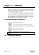
Chapter 1: Preface The Vigor3900 Series integrates a rich suite of functions, including NAT, firewall, VPN, load balance, and bandwidth management capability. These products are very suitable for providing multi-integrated solutions to SME markets. A Virtual Private Network (VPN) is an extension of a private network that encompasses links across shared or public networks like an Intranet.
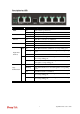
Description for LED LED Status Explanation PWR On The router is powered on. Off The router is powered off. Blinking The system is active. On/Off The system is hanged. On The fiber connection is established. Off No fiber connection is established. On The USB device is installed and ready. Off No USB device is installed. On The Ethernet link is established on corresponding port. Blinking The data transmission is done through the corresponding port.
Connectors Interface Description GigaLAN1 / 2 Connecter for local network devices. 3(SFP) Connecter for fiber cable. GigaWAN1/2/3/4 Connecter for remote network devices. 5(SFP) Connecter for fiber cable. Console Provided for technician use. USB1 / USB2 Connecter for the USB device. Factory Reset Used to restore the default settings. Press it and keep for more than 5 seconds. When you see the ACT LED begins to blink, release the button.
1.3 Hardware Installation 1.3.1 Network Connection Before starting to configure the router, you have to connect your devices correctly. 1. Connect one end of an Ethernet cable (RJ-45) to one of the LAN ports of Vigor3900s. 2. Connect the other end of the cable (RJ-45) to the Ethernet port on your computer (that device also can connect to other computers to form a small area network). The LAN LED for that port on the front panel will light up. 3.
1.3.2 Rack-Mounted Installation The Vigor3900 Series can be mounted on a rack by using standard brackets in a 19-inch rack or optional larger brackets on 23-inch rack (not included). The bracket for 19- and 23-inch racks are shown below. Attach the brackets to the chassis of a 19- or a 23-inch rack. The second bracket attaches the other side of the chassis as above procedure.
This page is left blank.
Chapter 2: Initialing Settings For use the router properly, it is necessary for you to change the password of web configuration for security and adjust primary basic settings. This chapter explains how to setup a password for an administrator and how to adjust basic settings for accessing Internet successfully. Be aware that only the administrator can change the router configuration. 2.
3. Now, the Main Screen will pop up. 4. Go to System Maintenance page and choose Administrator Password. 5. Enter the login password (admin) on the field of Original Password. Type a new one in the field of New Password and retype it on the field of Confirm Password. Then click Apply to continue. 6. Now, the password has been changed. Next time, use the new password to access the Web Configurator for this router.
2.2 Quick Start Wizard Quick Start Wizard is a wizard which is designed for configuring your router accessing Internet with simply steps. In the Quick Start Wizard group, you can configure the router to access the Internet with different modes such as Static, DHCP, PPPoE, or PPTP modes. For most users, Internet access is the primary application. The router supports the Ethernet WAN interface for Internet access. Click Quick Start Wizard from the home page.
Item Description Static - If Static is selected, you can manually assign a static IP address to the WAN interface and complete the configuration by applying the settings. DHCP - It allows a user to obtain an IP address automatically from a DHCP server on the Internet. If you choose DHCP mode, the DHCP server of your ISP will assign a dynamic IP address for Vigor3900 automatically. It is not necessary for you to assign any setting. (Host Name and Domain Name are required for some ISPs).
2.2.2 Step 2 - Configuring the Selected Protocol This page will be changed according to the IPv4 Protocol Type selected on last page. If Static is selected If Static is selected, the following screen will appear. You can manually assign a static IP address to the WAN interface and complete the configuration by applying the settings. Available parameters are listed as follows: Item Description IP Address Type a public IP address for such WAN profile.
DNS Server IP Address Add – Click this button to display the IP address field for adding a new IP address. Type the IP address on the tiny boxes one by one. Save – After finished the IP address configuration, click Save to save the setting onto the router. – Click the icon to remove the selected entry. Previous Click it to return to previous setting page. Finish Click it to finish the configuration. Cancel Click it to discard the settings configured in this page.
If DHCP is selected DHCP allows a user to obtain an IP address automatically from a DHCP server on the Internet. If you choose DHCP mode, the DHCP server of your ISP will assign a dynamic IP address for Vigor2960 automatically. It is not necessary for you to assign any setting. (Host Name is required for some ISPs). Available parameters are listed as follows: Item Description Host Name (Optional) Type a name as the host name for identification. Previous Click it to return to previous setting page.
Available parameters are listed as follows: Item Description Username Type in the username provided by ISP in this field. Password Type in the password provided by ISP in this field. Previous Click it to return to previous setting page. Finish Click it to finish the configuration. Cancel Click it to discard the settings configured in this page. When you finished the above settings, please click Finish.
If PPTP is selected This mode lets user get the IP group information by a DSL modem with PPTP service from ISP. Your service provider will give you user name, password, and authentication mode for a PPTP setting. Click PPTP as the protocol. Type in all the information that your ISP provides for this protocol. If your ISP offers you PPTP (Point-to-Point Tunneling Protocol) mode, please select PPTP for this router. Next, enter the settings provided by your ISP on the web page.
Server Address Type a remote IP address of PPTP server. Username Type in the username provided by ISP in this field. Password Type in the password provided by ISP in this field. Previous Click it to return to previous setting page. IP Address Type a public IP address for such WAN profile. Subnet Mask Choose the static mask from the drop down list. Gateway IP Address Type a public gateway address for such WAN profile. - click it to remove the IP address if you are not satisfied with it.
When you finished the above settings, please click Finish. Later, you can surf the Internet at any time. When the following screen appears, it means you have finished the Quick Start Wizard configuration.
2.3 Register Vigor Router Please follow the steps below to register the router. 1 Before using such function, please register your router online first. Log into the web configurator of Vigor3900 and click Product Registration. 2 A Login page will be shown on the screen. Please type the account and password that you created previously. And click Login.
3 The following page will be displayed after you logging in MyVigor. From this page, please click Add. Note: Below the field of Your Device List, all the Vigor routers that you have registered to MyVigor website will be displayed in sequence. 4 When the following page appears, please type in Nick Name (for the router) and choose the right registration date from the popup calendar (it appears when you click on the box of Registration Date).
5 Now, your router information has been added to the database. Click OK to leave this web page and return to My Information web page. 6 Take a look at the page of My Information, the new added Vigor3900 is listed under Your Device List.
Chapter 3: Application and Tutorial 3.1 How to Configure Load Balance with Multi-WAN on Vigor2960, Vigor300B or Vigor3900? There are two different LANs configured in the following figure. One is for Sale (192.168.1.1/24) and the other is for FAE (192.168.2.1/24). Sale's LAN will be configured to go Internet always via WAN1. When WAN1 is down, Sale's LAN will automatically failover to WAN2.
3. Click Add to open the following page. Type the information specified for LAN1 profile, then click Apply to save the settings and exit the screen. 4. Click Add again to create a profile for LAN2 (192.168.2.1/24).
Type the information specified for LAN2 profile, then click Apply to save the settings and exit the screen. 5. Open WAN >> Load Balance and click the Pool tab.
6. Click Add under the Pool tab to create a profile (e.g., WAN1WAN2) for automatic Load Balance between WAN1 and WAN2. Choose Load_Balance as the Mode option. 7. Click the Load_Balance tab to open the following page. Setup the Weights (e.g, “1”) of WAN1 and WAN2 as you want. In this case ratio of WAN1 and WAN2 is 1:1. Also, you can type 2 and 1 for WAN1 and WAN2, then the ratio of line speed of WAN 1and line speed of WAN 2 will be 2:1. 8.
9. Open WAN >> Load-Balance and click the Rule tab. 10. Click Add to create a profile for Rule1 accepting the data coming from 192.168.1.0/24 which always goes Internet via WAN1 when WAN1 is up. Type the information specified for such rule. (e.g., Rule1 for Profile; 192.168.1.0 for Source IP Address; wan1 for Load Balance Pool/WAN Profile and so on). Next, click Apply to save and exit.
11. Click Add again to create a profile for Rule2 accepting 192.168.2.0/24 which always goes Internet via WAN2 when WAN2 is up. 12. After clicking Apply, the created profiles will be shown on the screen. 13. Next, open WAN >> Default Route. Choose the profile of “WAN1WAN2” as WAN Profile/Loadbalance Pool Name. Note: The priority of WAN >> Load Balance>>Rule is higher than WAN >> Default Route. Now, you have completed the configuration.
3.2 How to Configure OSPF? OSPF (Open Shortest Path First) uses the algorithm of SPF (Shortest Path First) to calculate the route metric. It is suitable for large network and complicated data exchange. Both Vigor2960 and Vigor3900 support up to OSPF version 2(only for IPv4). The Autonomous System (AS) used in OSPF indicates the largest entity and can be divided into several areas. Usually, Area 0 will be used as OSPF backbone which distributing the routing information among areas.
Configuration for Vigor3900 A, 1. Open LAN >> General Setup to create a LAN (192.168.1.1/24) profile named lan1 with the settings shown below. 2. Next, continue to create a LAN (192.168.3.1/24) profile named lan2 with the settings shown below. 3. Open LAN >> Static Route and click the Inter-LAN Route tab to enable this profile.
4. Open LAN >> OSPF Configuration to enable this profile. Click Add to make the LAN Profiles lan2 area setting as 11 and lan1 area as 11. (As shown in the topology diagram.) Configuration for Vigor3900 B, 1. Open LAN >> General Setup to create a LAN (192.168.2.1/24) profile named lan1 with the settings shown below. 2. Next, continue to create a LAN (192.168.3.2/24) profile named lan2 with the settings shown below.
3. Open LAN >> Static Route and click the Inter-LAN Route tab to enable this profile. 4. Open LAN >> OSPF Configuration to enable this profile. Click Add to make the LAN Profiles lan2 area setting as 11 and lan1 area as 11. (As shown in the topology diagram.) Configuration for Vigor2960, 1. Open LAN >> General Setup to create a LAN (192.168.4.1/24) profile named lan1 with the settings shown below.
2. Next, continue to create a LAN (192.168.3.3/24) profile named lan2 with the settings shown below. 3. Open LAN >> Static Route and click the Inter-LAN Route tab to enable this profile. 4. Open LAN >> OSPF Configuration to enable this profile. Click Add to make the LAN Profiles lan2 area setting as 11 and lan1 area as 11. (As shown in the topology diagram.
5. After setting, check the routing information (marked with red line) which is created by OSPF.
3.3 How to Configure LAN to LAN IPSec Tunnel between Vigor3900 and Other Router (Main Mode) Here provides an example about LAN to LAN IPSec tunnel established between Vigor3900 and Vigor2710. Configuring Vigor3900 1. Access into the web configurator of Vigor3900 and open VPN and Remote Access >> LAN to LAN Profiles to add a new VPN configuration. Type the Pre-shared key and choose a WAN Profile. Specify Local IP/Subnet Mask with 192.168.29.0/24.
Configuring Vigor2710 1. 2. In Vigor2710, it is necessary to build two VPN connections (for two WANs) to connect with Vigor3900. Please open the web configurator of Vigor2710 and open VPN and Remote Access >> LAN to LAN. z First, please type the name of such VPN connection in the field of Profile Name (e.g., 3900). z Check the box of Enable this profile. z Choose Dial-Out as Call Direction and check the box of Always on.
3. For the role of Vigor2710 is dialing-out, please skip Dial-In setting. Type the Remote Network IP and Remote Network Mask of Vigor3900 to complete configuration. 4. Please check if the VPN connection is built successfully in both devices respectively. For Vigor3900, open VPN and Remote Access>>IPSec>>Status for viewing the result. As to Vigor2710, please open VPN and Remote Access>>Connection Management to confirm the result.
3.4 How to run RDP service in the browser via logging in 3900's HTTPS Server? Remote Desktop Protocol (RDP) is a protocol designed for secure communications in networks using Microsoft Terminal Services. An easy way is provided to establish connection between the router and the RDP Server via any browser. 1. Open the web configurator of Vigor3900. 2. Enable the HTTPS service from System Maintenance >> Access Control by clicking Enable for HTTPS Allow and type 443 as the value of HTTPS Port.
3. Open SSL VPN >> SSL Application and click the RDP tab to create a profile named “Win7”. Type IP address, Port number, and Screen Size as you want, then click Apply to save the settings. 4. Open User Management >> User Profile to create a new profile named “7788”. Set the Password as 7788 and choose the profile of Win7 as SSL Application (RDP). Click Apply. 5. Logout Vigor3900. 6. Login Vigor3900 HTTPS Server with 7788 for both Username and Password.
7. A screen like the following figure will appear. Simply click the SSL Application link. 8. In the following screen, click Connect for connecting to Win7, the RDP server.
9. After that, you can access into Windows 7 via a browser. Note the message below the window. In which, TLS means Transport Layer Security.
Troubleshooting If you have installed Java Runtime Environment edition 6 but still cannot establish the connection, please make sure you have disabled “Use TLS 1.0” in the Java Control Panel as figure shown below. Then, try to connect again.
3.5 How to Configure VPN Load Balance between Vigor3900 and Other Router The staff in branch office can access into mail server/FTP server installed in the headquarters via VPN Load Balance tunnels. Refer to the following figure. Vigor3900 allows users to build VPN load balance connection between Vigor3900 and other router. Take Vigor2950 for an example. There are two WANs on Vigor2950 and two WANs on Vigor3900.
2. Create a profile for WAN 1 (named 2950WAN1).
3. Click Apply to save the settings and exit the dialog. 4. Create a profile for WAN 2 (named 2950WAN2).
5. Click Apply to save the settings and exit the dialog. 6. Open VPN and Remove Access>>VPN Trunk Management and click the Load Balance Pool tab. Click Add to add a Load Balance Pool profile. 7. The following window will pop up. Give a name for the profile. 8. Click the Load Balance tab. Select the IPSec GRE profiles (e.g., 2950WAN1) set for Vigor2950 then click Apply.
9. Click the Load Balance Rule tab and click Add to add a Load Balance rule profile. 10. Enable this profile and input the following settings then click Apply. Type the local network IP address and Mask of Vigor3900 as Source IP Address and Source Mask; type the network IP and Mask of Vigor2950 as Destination IP Address & Destination Mask. Select the Load Balance Pool profile (e.g., 2950_LB) set for Vigor2950.
Configuring Vigor2950 1. In Vigor2950, it is necessary to build two VPN connections (for two WANs) to connect with Vigor3900. Please open the web configurator of Vigor2950 and open VPN and Remote Access >> LAN to LAN. z First, please type the name of such VPN connection in the field of Profile Name (e.g., 3900WAN1). z Choose WAN1 Only as VPN Dial-Out Through setting to specify which WAN interface will be used for building VPN connection.
z 2. Please type the network IP address and subnet of Vigor3900 in the field of Remote Network IP and Remote Network Mask. Type the network IP address and subnet of Vigor2950 in the field of Local Network IP and Local Network Mask. Continue to set the second VPN connection (profile name is 3900WAN2). The first VPN tunnel will be used by WAN1 of Vigor2950. The second VPN tunnel will be configured for the WAN2 of Vigor2950. Therefore, please choose WAN2 Only for VPN Dial-Out Through.
z Next, type the Network IP and Network Mask for both remote and local ends to complete the second VPN connection. 3. After finished the settings on both VPN connections, please access the web configurator of Vigor2950 and open VPN and Remote Access > VPN Trunk Management to make these two VPN connections into one Load Balance group. 4. Type the name (e.g., 3900) of the Load Balance in the field of Profile Name. Specify the VPN profiles in Member 1 and Member 2 respectively.
As to Vigor2950, please open VPN and Remote Access>>Connection Management to confirm the result.
3.6 How to Setup 50 WANs on Vigor3900 Vigor3900 has 5 physical WANs; however, it can be extended to 50 WANs at most by using VLAN Tagging technology. Below will show how to achieve 50 WANs setup by one Vigor3900 and two VigorSwitch2260s. Refer to the following application illustration: Configuring 50 WAN profiles on Vigor3900 1. Change mode from Basic to Advance via WAN>>General Setup page.
2. Click OK. Vigor3900 will ask you to re-login. 3. Delete default wan profiles for wan3, wan4 and wan5 by selecting the wan profile then click Delete. 4. Click Add to add new WANs.
5. Create a new WAN profile named with wan1_1, and set VLAN ID named with 111 based on WAN Port 1(WAN1). Note that Untag must be set with Disable. It means wan1_1 can accept the packets tagged with VLAN ID 111. Next, click Apply to save the settings. 6.
3. 4. Type VLAN name and VID with 111. z Suppose the physical WAN1 of Vigor3900 connects to Port 26 of VigorSwitch. Port 26 will receive untagged packets (based on profile wan1) and packets tagged with 111 to 134 (based on profiles wan1_1 to wan1_24). Therefore VigorSwitch Port 26 must be the member of VLAN Group ID 111 to 134. z In Member field, select Port 1 and Port 26 as members of VLAN Group 111. Member setting means only the selected port number (e.g.
5. 6. Go to VLAN>>PVID page to set up PVID for each port. z PVID means VigorSwitch2260 will check and add VLAN tags while receiving packets from Ports. z ISP modem 1 which connects to Port 1 doesn’t support VLAN Tag. z While the switch receives packets from Port 1, it will add VLAN Tag 111 to the packets Then Vigor3900 wan1_1 will receive the packets. After finishing the configuration for one VigorSwitch, please set for another VigorSwitch with the same procedure.
Chapter 4: Advanced Web Configuration After finished basic configuration of the router, you can access Internet with ease. For the people who want to adjust more setting for suiting his/her request, please refer to this chapter for getting detailed information about the advanced configuration of this router. As for other examples of application, please refer to chapter 3. 4.1 WAN Setup Quick Start Wizard offers user an easy method to quick setup the connection mode for the router.
via PAP or CHAP with RADIUS authentication system. And your IP address, DNS server, and other related information will usually be assigned by your ISP. 4.1.1 General Setup This section will introduce some general settings of Internet and explain the connection modes for WAN profiles in details. This router supports multi-WAN function. It allows users to access Internet and combine the bandwidth of the WAN profiles to speed up the transmission through the network.
If you switch into Advance mode, you will get the following page: Each item will be explained as follows: Item Description Add Add a new WAN profile. Edit Modify the selected WAN profile. To edit a profile, simply select the one you want to modify and click the Edit button. The edit window will appear for you to modify the corresponding settings for the selected rule. Delete Remove the selected WAN profile. To delete a profile, simply select the one you want to delete and click the Delete button.
How to add a new WAN profile 1. First, you have to switch into Advance mode. 2. A confirmation dialog will appear. Click OK to apply the related settings for Advance mode. 3. Re-login the system. 4. Open WAN>>General Setup. Click the Add button to open the following dialog. Different protocol type selected will bring up different configuration web page. Available parameters are listed as follows: Item Description Profile Type a name for such profile.
VLAN Tag Choose Enable to tag the packets passing through the port specified below. Port Choose the physical WAN interface for such profile. Default MAC Address Enable – Click it to enable the default MAC address for such profile. Disable – Click it to type the MAC address manually for such profile. MAC Address Specify the MAC address for such profile. In default, the system will determine it automatically. Mode Determine such profile will be used for.
Different IPv4 and IPv6 protocol types specified will bring up different configuration web page. z If you choose Static as IPv4 protocol type, click the Static Tab to open the following page: Available parameters are listed as follows: Item Description IP Address Type the IP address specified for such profile. Subnet Mask Use the drop down list to choose the subnet mask for such profile. Gateway IP Address Type the gateway address for such profile.
NAT>>Port Redirection/DMZ Host). To add a new IP address, simply type the IP address on the box near to the Add button. Next, click Add. The new one will be added and displayed on the field under the box. Add – click this button to have a field for adding a new IP address. Save – Click this button to save the setting. – click the icon to remove the selected entry. MTU/MRU Type the value of MTU/MRU. The default value is 1500. Connection Detection Mode Select a detecting mode for this WAN interface.
z Apply Click it to save the configuration and exit the dialog. Cancel Click it to exit the dialog without saving the configuration. If you choose DHCP as IPv4 protocol type, click the DHCP Tab to open the following page: Available parameters are listed as follows: Item Description Host Name (Optional) Type a name as the host name for identification. IP Alias Type other IP addresses to be bound to this interface. This setting is optional.
address. Save – click this button to save the setting. – click the icon to remove the selected entry. MTU/MRU It means Max Transmit Unit for packet. The default setting is 1500. Connection Detection Mode Select a detecting mode for this WAN interface. There are three ways ARP, PING and HTTP supported in Vigor router for you to choose to send the request out.
z If you choose PPPoE as IPv4 protocol type, click the PPPoE Tab to open the following page: Available parameters are listed as follows: Item Description Username Type the user name offered by your ISP. Password Type the password offered by your ISP. MTU/MRU Type the value of MTU/MRU. The default value is 1492. Debug Click Enable to display the PPPoE debug message in Syslog. The default setting is Disable. Always On Enable – Click it to enable the function of Always On.
Add – click this button to have a field for adding a new IP address. Save – click this button to save the setting. – click the icon to remove the selected entry. Connection Detection Interval Assign an interval period of time for each detecting. Connection Detection Retry Assign detecting times to ensure the connection of the WAN interface. After passing the times you set in this field and no reply received by the router, the connection of WAN interface will be regarded as breaking down.
z If you choose PPTP as IPv4 protocol type, click the PPTP Tab to open the following page: Available parameters are listed as follows: Item Description PPTP Over Usually ISP dynamically assigns IP address to you each time you connect to it and request. In some case, your ISP provides service to always assign you the same IP address whenever you request. In this case, you can fill in this IP address in the Fixed IP field. Please contact your ISP before you want to use this function.
Connection Detection Host If you choose PING/HTTP as Connection Detection Mode, you have to specify the detection host address in this field. Use the default setting. Add – click this button to have a field for adding a new IP address. Save – click this button to save the setting. – click the icon to remove the selected entry. z Connection Detection Interval Assign an interval period of time for each detecting.
z If you choose Static as IPv6 protocol type, click the StaticV6 tab to open the following page: Available parameters are listed as follows: Item Description IPv6 Address Type the IP address for such protocol. IPv6 Prefix Length Type your IPv6 address prefix length. IPv6 Gateway Address Type your IPv6 gateway address. IPv6 DNS Server Address Type your IPv6 primary DNS Server address. Add – click this button to have a field for adding a new IP address.
z If you choose DHCP-IA_NA as IPv6 protocol type, click the DHCPV6 Tab to open the following page: Available parameters are listed as follows: Item Description DHCP (IA_NA) Gateway Address Type the gateway IP address for IPv6 DHCP IA_NA mode. DHCP (IA_NA) DNS Address Type your IPv6 primary DNS Server address. Add – click this button to have a field for adding a new IP address. Save – click this button to save the setting. – click the icon to remove the selected entry.
4.1.2 Default Route This page allows you to assign a WAN profile or a Load Balance profile as the default route. Available parameters are listed as follows: Item Description WAN Profile /Load Balance Pool Name Display the WAN profiles for user to choose as a default route. In which, wan1 to wan5 are factory default settings. Refresh Renew the page configuration. Apply Click it to save the configuration.
4.1.3 Load Balance Policy Vigor3900 supports a load balancing function. It can assign traffic with protocol type, IP address for specific host, a subnet of hosts, and port range to be allocated in WAN interface. User can assign traffic category and force it to go to dedicate network interface based on the following web page setup. In the WAN group, click the Load Balance Policy option.
Protocol Display the protocol of such rule. Source IP Address Display the WAN IP address here as the source IP address for such rule. Source Mask Display the mask for the source. Destination IP Address Display the WAN IP address here as the destination IP address for such rule. Destination Mask Display the mask for the destination. Destination Port Start Display the starting port value for the destination. Destination Port End Display the ending port value for the destination.
Item Description Profile Type the name of the rule. Enable This Profile Check this box to enable such profile. Protocol Choose a protocol (ALL, TCP, UDP, ICMP, FTP, TFTP, HTTP, SMTP, POP3, TCP/UDP) for such rule applied to load balance. All is the default setting. Source IP Address Type a WAN IP address here as the source IP address for such rule. – click the icon to clear the IP setting. Source Mask Use the drop down list on the right to choose a suitable mask for the source.
4. Enter all the settings and click Apply. The new rule profile will be added on the screen. Pool This page allows the user to integrate several WAN profiles as a pool profile specified with the function of load balance or failover. The profiles configured here will be selected in the field of WAN>>Default Route page. Each item will be explained as follows: Item Description Add Add a new pool profile. Edit Modify the selected pool profile.
Mode Display the mode (failover or load balance) used by the pool profile. Interface Display the name of the WAN profiles for Load Balance rule. Primary Profile Display the primary profile configured in Failover page for such profile. Backup Profile Display the backup profile configured in Failover page for such profile. There are two modes, Load_Balance and Failover, for you to choose as the Pool configuration.
3. Click the Load_Balance Tab. 4. Click Add. A new line for adding new entry will appear. 5. Use the drop down list of Interface to choose the WAN profiles that will be in the Load Balance Pool. Type the value for Weight. 6. Click Apply. A new profile will be added on the page.
How to add a Pool profile for Failover Such page allows you to set a backup profile which will be activated when the primary profile is invalid by any reason. 1. Open WAN>>Load Balance Policy and click the tab of Pool. 2. Simply click the Add button to open the following dialog. Type a name (e.g., FL_1) for such profile. Choose Failover as the Mode selection. 3. Click the Failover Tab. In default, the system will apply Primary Profile.
4. Use the drop down list to choose the one you need. “wan1” to wan5” are default settings. 5. Click Apply. A new profile will be added on the page. 4.1.4 Switch This page allows you to configure Mirroring Port, Mirrored Port, enable/disable WAN interface, and configure 802.1Q VLAN ID for different WAN interfaces, and so on. 802.1Q VLAN Configuration Packets passing through the WAN interface might be tagged or untagged with VLAN ID number.
This page simply displays current status of 802.1Q VALN setting profiles. Each item will be explained as follows: Item Description Refresh Click it to reload this page. VLAN ID Display the VLAN ID number. Member Display number of the WAN interface for the packets tagged with such VLAN ID number to pass through. Untag Display number of the WAN interface for the VLAN ID will be untagged for packets passing through the WAN interface selected.
Mirror Configuration The administrator can monitor all the packets passing through mirrored port with the mirroring port. It is useful for the administrator to analyze the troubles on Network. Available parameters are listed as follows: Item Description Enable This Profile Check the box to enable the Mirror function for the switch. Mirroring Port Select a port for the administrator to use for viewing traffic sent from mirrored ports.
Interface Configuration This page allows you to modify the status (enable / disable), speed(Auto,10M,100M,1000M) and duplex (Half/Full) for the WAN ports respectively. Each item will be explained as follows: Item Description Edit Choose the interface listed below and click the Edit button to modify the settings. A pop up window will appear for you to change the settings. Interface – Display the name of WAN interface. Enable This Profile – Check it to enable such interface.
means enabled. Duplex Display the duplex used (full or half) by such profile. Speed Display the transmission rate (10M, 100M, 1000M or Auto) of the date for such profile. Status of the Switch This page provides information about speed, duplex, port connection (UP or Down) for the WAN ports. Available parameters are listed as follows: Item Description Refresh Renew current web page. Auto Refresh Specify the interval of refresh time to obtain the latest status.
4.2 LAN Local Area Network (LAN) is a group of subnets regulated and ruled by router. The design of network structure is related to what type of public IP addresses coming from your ISP. The most generic function of Vigor router is NAT. It creates a private subnet of your own. As mentioned previously, the router will talk to other public hosts on the Internet by using public IP address and talking to local hosts by using its private IP address.
Edit Modify the selected LAN profile. To edit a profile, simply select the one you want to modify and click the Edit button. The edit window will appear for you to modify the corresponding settings for the selected rule. Delete Remove the selected LAN profile. To delete a rule, simply select the one you want to delete and click the Delete button. Refresh Renew current web page Profile Display the name of the LAN profile. Enable This Profile Display the status of the profile.
Available parameters are listed as follows: Item Description Profile Type the name of the LAN profile. Enable This Profile Check this box to enable such profile. Description Type the description for the new LAN profile. VLAN ID Type a number as the VLAN ID to make the data be identified while performing data transmission. Default MAC Address Enable – Click it to enable the default MAC address for such profile. Disable – Click it to type the MAC address manually for such profile.
Add – Click it to add a new subnet mask with IP address and specified mode. Save – Click it to save the settings. IP – Type the IP address if you click Add for adding a new entry. Subnet Mask – Use the drop down list to choose the one you want. Mode – Specify NAT or Routing as the mode. – click the icon to remove the selected entry. IPv6 Protocol It defines the IPv6 connection types for LAN interface. Possible types contain Link-Local, Static and DHCP-SLA.
3. When you finish the above settings, please click Apply to save the configuration and exit the dialog. DHCP In the Vigor3900 router, there are some IP address settings for the LAN interface. The IP address/subnet mask is for private users or NAT users. The IP address of the default gateway on other local PCs should be set as the Vigor3900 server IP address. When the DSL connection between the DSL and the ISP has been established, each local PC can directly route to the Internet.
Enable This Profile Display the status of the profile. False means disabled; True means enabled. Start IP Display the starting IP address of the IP address pool for DHCP server. End IP Display the ending IP address of the IP address pool for DHCP server. DNS Display the IP address for DNS. Routers In general, this box will be blank. It means Vigor3900 will be regarded as the gateway for the user. Lease Time Display the lease time for the DHCP server.
Available parameters are listed as follows: Item Description Profile Display the name of the LAN profile. Enable This Profile Check this box to enable this profile. Start IP Set the starting IP address of the IP address pool for DHCP server. End IP Set the ending IP address of the IP address pool for DHCP server. DNS Set the private IP address for DNS server. If this field is blank, users on LAN will treat Vigor3900 as the DNS server. Add – Click it to add a new IP address for DNS server.
– click the icon to clear the IP setting. Lease Time Set a lease time for the DHCP server. The time unit is minute. Specify Remote Dial-in IP Enable – Enable this function that remote clients within the range specified below can access into Vigor3900 WUI. Disable – Disable this function. Remote Dial-in Start IP Specify the start IP address for an IP range. The DHCP server can assign an IP address for remote dial-in user from such IP range.
rule. Refresh Renew current web page. Profile Display the name of the LAN profile. Enable This Profile Display the status of the profile. False means disabled; True means enabled. DHCP Server Location Display the LAN or WAN profile for the DHCP server. DHCP Server IP Display the IP address of DHCP server. How to edit a LAN profile for DHCP Relay 1. Open LAN>>General Setup and click the DHCP Relay tab. 2.
Cancel Click it to exit the dialog without saving anything. 3. When you finish the above settings, please click Apply to save the configuration and exit the dialog. 4. The LAN profile has been edited. RADVD The router advertisement daemon (radvd) sends Router Advertisement messages, specified by RFC 2461, to a local Ethernet LAN periodically and when requested by a node sending a Router Solicitation message. These messages are required for IPv6 stateless auto-configuration.
Profile Display the name of the LAN profile. Enable This Profile Display the status of the profile. False means disabled; True means enabled. Advertisement Lifetime Display the lifetime value. The lifetime associated with the default router in units of minutes, ranging from 10 ~ 150. It is used to control the lifetime of the prefix. A lifetime of 0 indicates that the router is not a default router and should not appear on the default router list. How to edit a LAN profile for RADVD 1.
Cancel Click it to exit the dialog without saving anything. 3. When you finish the above settings, please click Apply to save the configuration and exit the dialog. 4. The LAN profile has been edited. DHCP6 DHCP6 Server could assign IPv6 address to PC according to the Start/End IPv6 address configuration. Each item will be explained as follows: Item Description Edit Modify the selected LAN profile. To edit a profile, simply select the one you want to modify and click the Edit button.
means enabled. Start IP Display the starting IP address of the IP address pool for DHCP server. End IP Display the ending IP address of the IP address pool for DHCP server. DNS Display the private IP address for DNS server. How to edit a LAN profile for DHCPv6 1. Open LAN>>General Setup and click the DHCPv6 tab. 2. Choose one of the LAN profiles by clicking on it and click the Edit button to open the following dialog.
following example: 2000:0000:0000:0000:0000:0000:0000:10 or 2000::10. End IP Set the ending IP address of the IP address pool for DHCP server. The format the IP address shall be similar to the following example: 2000:0000:0000:0000:0000:0000:0000:10 or 2000::10. DNS Set the private IP address for DNS server. If this field is blank, users on LAN will treat Vigor3900 as the DNS server. Add – Click it to add a new IP address for DNS server. Save – Click it to save the setting.
4.2.2 IP Routing To make local device in LAN accessing into external network without passing NAT or let the remote device access into the local device without passing NAT behind the router, please use IP routing function to complete the work. Usually, the local device might be assigned with a public IP address or an IP address with the same subnet as certain WAN.
LAN Profile Display which LAN profile used for the local device. IP Display the private IP address for such profile. Mask Display the subnet mask for such profile. How to add a new IP Routing profile 1. Open LAN>>IP Routing. 2. Click the Add button. 3. The following dialog will appear. Available parameters are listed as follows: Item Description Profile Type the name of the IP routing profile. Enable This Profile Check this box to enable such IP routing profile.
4. Enter all the settings and click Apply. The new profile will be added on the screen. 4.2.3 Static Route When there are several subnets in LAN or WAN, a more effective and quicker way for connection is static route rather than other methods. Simply set rules to forward data to specified subnet through the specific gateway. Static Route Each item will be explained as follows: Item Description Add Add a new static route setting. Edit Modify the selected static route setting.
Profile Display the name of such static route. Enable This Profile Display the status of the profile. False means disabled; True means enabled. Destination IP Address Display the IP address for such static route profile. Subnet Mask Display the subnet mask for such static route profile. Gateway Display the gateway address for such static route profile. WAN/LAN Profile Display the subnet / LAN or WAN profile of the gateway. Metric Display the distance to the target.
5. Destination IP Address Type the IP address for such static route profile. Subnet Mask Use the drop down list to choose the subnet mask for such static route profile. Gateway Type the gateway address for such static route profile. WAN/LAN Profile Choose one of the LAN/WAN profiles of the gateway for such static route. Metric Type the distance to the target (usually counted in hops). Apply Click it to save and exit the dialog. Cancel Click it to exit the dialog without saving anything.
IPv6 Static Route For IPv6 protocol, click the IPv6 Static Route tab to configure detailed settings. Each item will be explained as follows: Item Description Add Add a new static route setting. Edit Modify the selected static route setting. To edit static route setting, simply select the one you want to modify and click the Edit button. The edit window will appear for you to modify the corresponding settings for the selected rule. Delete Remove the selected static route setting.
How to add a new IPv6 Static Route profile 1. Open LAN>>Static Route and click the IPv6 Static Route tab. 2. Click the Add button. 3. The following dialog will appear. Available parameters are listed as follows: Item Description Profile Name Type the name of the static route profile. Enable This Profile Check this box to enable such profile. Destination IP Address Type the IP address for such static route profile. Prefix Length Type the prefix length for such profile.
4. Enter all the settings and click Apply. The new profile will be added on the screen. Inter-LAN Route To make the users in different LAN communicating with each other, please check the box to enable Inter-LAN route function.
4.2.4 Switch This page allows you to configure Mirroring Port, Mirrored Port, enable/disable LAN interface, and configure 802.1Q VLAN ID for different LAN interfaces, and so on. 802.1Q VLAN Virtual LANs (VLANs) are logical, independent workgroups within a network. These workgroups communicate as if they had a physical connection to the network. However, VLANs are not limited by the hardware constraints that physically connect traditional LAN segments to a network.
selected rule. Delete Remove the selected VLAN ID setting. To delete a VLAN ID setting, simply select the one you want to delete and click the Delete button. Refresh Renew current web page. VLAN ID Display the VLAN ID number. Member Display the LAN interface that is used to access into Internet for such LAN profile with the VLAN ID number. Untag Display the LAN interface that packets transmitted to Internet through such LAN profile with the VLAN ID number is tagged or untagged.
Internet for such LAN profile with the VLAN ID number. 4. Untag Determine if the packets transmitted to Internet through such LAN profile with the VLAN ID number is tagged or not. Apply Click it to save and exit the dialog. Cancel Click it to exit the dialog without saving anything. Enter all the settings and click Apply. The new profile will be added on the screen. Mirror Vigor3900 supports port mirroring function in LAN interfaces.
Available parameters are listed as follows: Item Description Enable This Profile Check the box to enable the Mirror function for the switch. Mirroring Port Select a port to view traffic sent from mirrored ports. Mirrored Port Select which port is necessary to be mirrored. Refresh Renew current web page. Apply Click it to save the settings. Interface This page allows you to modify the status (enable / disable), speed(Auto,10M,100M,1000M) and duplex (Half/Full) for the LAN ports respectively.
Refresh Renew current web page. Interface Display the profile name of the interface. Enable This Profile Display the status of the profile. False means disabled; True means enabled. Duplex Display the duplex used (full or half) by such profile. Speed Display the transmission rate (10M, 100M, 1000M or Auto) of the date for such profile. How to edit an Interface profile 1. Open LAN>>Switch and click the Interface tab. 2. Please select a profile and click the Edit button. 3.
4. Duplex Use the drop down list to choose the duplex for such profile. Speed Use the drop down list to specify the transmission rate for such profile. Apply Click it to save and exit the dialog. Cancel Click it to exit the dialog without saving anything. Enter all the settings and click Apply. The profile has been edited. Status This page displays the status the status (enable / disable), speed(Auto,10M,100M,1000M) and duplex (Half/Full) of the LAN ports respectively.
4.2.5 Bind IP to MAC This function is used to bind the IP and MAC address in LAN to have a strengthen control in network. When this function is enabled, all the assigned IP and MAC address binding together cannot be changed. If you modified the binding IP or MAC address, it might cause you not access into the Internet. Each item will be explained as follows: Item Description Mode Enable - Choose it to invoke this function. However, IP/MAC which is not listed in IP Bind List also can connect to Internet.
Delete You can remove any item listed in IP Bind List. Simply click and select the one, and click Delete. The selected item will be removed from the IP Bind List. Select All Choose all of the selections at one time. Refresh It is used to refresh the ARP table. When there is one new PC added to the LAN, you can click this link to obtain the newly ARP table information. Rename Allow to modify the selected profile name. Bind Table It displays a list for the IP bind to MAC information.
3. Click Add. 4. The following dialog appears. Available parameters are listed as follows: Item Description Profile Type the name of the profile. IP Address Type the IP address that will be used for the specified MAC address. MAC Type the MAC address that is used to bind with the assigned IP address. Apply Click it to save and exit the dialog. Cancel Click it to exit the dialog without saving anything. 5. Enter all the settings and click Apply. 6.
4.2.6 RIP Configuration The Routing Information Protocol (RIP) is a dynamic routing protocol used in local and wide area networks. The routing information packet will be sent out by web server or router periodically, and can be used to communicate with other routers. It will calculate the number of network nodes on the route to ensure there is no obstruction on the network routine.
Available parameters are listed as follows: Item Description Enable This Profile Check the box to enable the Mirror function for the switch. Profile Choose one of the LAN profiles. Apply Click it to save the settings. Cancel Click it to discard the settings configured in this page. 4.2.7 OSPF Configuration OSPF uses the algorithm of SPF (Shortest Path First) to calculate the route metric. It is suitable for large network and complicated data exchange.
Available parameters are listed as follows: Item Description Enable This Profile Check the box to enable the Mirror function for the switch. Profile Type a new name for such profile. Apply Click it to save the settings. Cancel Click it to cancel the settings configuration. How to add a new profile 1. Open LAN>>OSPF Configuration. 2. Check Enable This Profile. 3. Click the space of Profile. A pop-up dialog will appear. Click Add.
4. Use the drop down list of LAN Profile to choose the one you need. And specify the value of Area (either 0.0.0.0 ~ 255.255.255.255 or 0 ~ 4294967295) for that profile. If you are not satisfied the settings, simply click re-type the settings. 5. to remove the entry, and then Click Apply to save the settings and exit the dialog. A new profile is created and displayed on the screen.
4.3 NAT NAT (Network Address Translation) is a method of mapping one or more IP addresses and/or service ports into different specified services. It allows the internal IP addresses of many computers on a LAN to be translated to one public address to save costs and resources of multiple public IP addresses. It also plays a security role by obscuring the true IP addresses of important machines from potential hackers on the Internet.
Each item will be explained as follows: Item Description Add Add a new port redirect profile. Edit Modify the selected profile. To edit a profile, simply select the one you want to modify and click the Edit button. The edit window will appear for you to modify the corresponding settings for the selected rule. Delete Remove the selected profile. To delete a profile, simply select the one you want to delete and click the Delete button. Refresh Renew current web page.
How to add a new Port Redirection profile 1. Open NAT>> Port Redirection. 2. Simply click the Add button. 3. The following dialog will appear. Available parameters are listed as follows: Item Description Profile Type the name of the profile. Enable This Profile Check the box to enable this profile. Interface Specify the WAN profile for such profile.
Use IP Alias Use the drop down list to select the one you want. IP Alias WAN IP alias that can be selected and used for port redirection. Before using it, please go to WAN>>General Setup and enable the wan1 profile. Add several IP addresses under Static mode for wan1. Private IP Specify the private IP address of the internal host providing the service. Simply type the private IP used for this entry. Protocol Choose the protocol used for the entry.
4.3.2 DMZ Host In computer networks, a DMZ (De-Militarized Zone) is a computer host or small network inserted as a neutral zone between a company’s private network and the outside public network. It prevents outside users from getting direct access to company network. A DMZ is an optional and more secure approach to a firewall and effectively acts as a proxy server as well.
rule. Delete Remove the selected profile. To delete a profile, simply select the one you want to delete and click the Delete button. Refresh Renew current web page. Rename Allow to modify the selected profile name. Profile Display the name of the profile. Enable The Profile Display the status of the profile. False means disabled; True means enabled. WAN Profile Display the WAN profile that such DMZ host profile will be applied to. Private IP Display the private IP used for this entry.
3. The following dialog will appear. Available parameters are listed as follows: Item Description Profile Type the name of the profile. Enable This Profile Check the box to enable the DMZ Host profile. WAN Profile Choose a WAN profile for such entry. Private IP Type the private IP used for this entry. Use IP Alias Click Enable to invoke IP Alias function. IP Alias IP alias that can be selected and used for port redirection.
4.3.3 Address Mapping This page is used to map specific private IP to specific WAN IP alias. If you have "a group of IP Addresses" and want to apply to the router, please use WAN IP alias function to record these IPs first. Then, use address mapping function to map specific private IP to specific WAN IP alias. For example, you have IP addresses ranging from 86.123.123.1 ~ 86.123.123.8. However, your router uses 86.123.123.1, and the rest of the IPs are recorded in WAN IP alias. You want that private IP 192.
will be applied to. Private IP Display the private IP used for this entry. Private IP Subnet Mask Display the subnet mask used for this entry. Protocol Display the protocol used for the entry. Use IP Alias Display the using status (enabled or disabled) for WAN IP alias. IP Alias Display the selected WAN IP address. How to add a new Address Mapping profile 1. Open NAT>> Address Mapping. 2. Simply click the Add button. 3. The following dialog will appear.
Private IP subnet Mask Type the subnet mask used for this entry. Protocol Choose the protocol used for the entry. Use IP Alias Click Enable to invoke IP Alias function. IP Alias Select the Alias IP for this Address Mapping profile. Apply Click it to save and exit the dialog. Cancel Click it to exit the dialog without saving anything. 4. Enter all the settings and click Apply. 5. A new profile has been added onto Address Mapping table.
4.3.4 SIP ALG SIP ALG means Session Initiation Protocol, Application Layer Gateway. This page allows you to choose LAN and WAN profiles for Vigor router to make SIP message and RTP packets of voice being transmitting and receiving correctly via NAT. Available parameters are listed as follows: Item Description Enable This Profile Check the box to enable the Mirror function for the switch. LAN Interface Choose one of the LAN profiles. WAN Interface Choose one of the WAN profiles.
4.4 Firewall The firewall controls the allowance and denial of packets through the router. The Firewall Setup in the Vigor3900 Series mainly consists of packet filtering, Denial of Service (DoS) and URL (Universal Resource Locator) content filtering facilities. These firewall filters help to protect your local network against attack from outsiders.
IP Filter This page allows you to create new IP filter rule(s) and group them for your request. The upper part displays the information of IP Filter Group(s); the lower part displays the information of IP Filter Rule(s). You should create at least one IP filter rule and one group profile. The following will explain IP Filter functions with details. Each item will be explained as follows: Item Description IP Filter Rule Group Add Add a new group profile for IP filter. Edit Modify the selected profile.
Item Description Comment Display the description for such profile. IP Filter Rule Group of Selected Group Add Add a new IP filter rule profile. Before you create an IP filter rule, you have to create an IP filter group first. Otherwise, you are not allowed to add any IP filter rule here. Edit Modify the selected profile. To edit a profile, simply select the one you want to modify and click the Edit button. The edit window will appear for you to modify the corresponding settings for the selected rule.
3. The following dialog will appear. Available parameters are listed as follows: Item Description Group Type the name of the IP filter group. Enable This Profile Check the box to enable this profile. Comment Give a brief description for the profile. 4. Enter all the settings and click Apply. 5. A new filter group has been added onto Address Mapping table.
6. Choose the IP filter group first and then click the Add tab (the lower one in this page). 7. The following page for configuration will appear. Available parameters are listed as follows: Item Description Rule Type the name of the IP filter rule. Enable This Profile Check the box to enable this profile.
Time Profile Choose a schedule profile to be applied on such rule. You can click Source IP Choose one or more IP object profiles from the drop down list. The selected profile will be treated as source IP. You can click Destination IP to create another new IP object profile. Choose one or more IP object profiles from the drop down list. The selected profile will be treated as destination IP. You can click Service Type to create another new time object profile.
Apply Click it to save and exit the dialog. Cancel Click it to exit the dialog without saving anything. 8. Enter all the settings and click Apply. 9. A new IP filter rule has been added onto IP Filter Rules of Selected Group table. Note: You can create multiple IP filter groups. Each IP Filter Rules of Selected Group belongs to an IP Filter Rule Group. Click an IP Filter Rule Group to show its members in the lower display window.
Application Filter Application Filter can integrate several application objects within one profile for restricting the usage of application. For example, it can block people defined in IP object profile not using IM application, not using P2P for file sharing, and not downloading files via certain protocol. Each item will be explained as follows: Item Description Add Add a new group profile for Application filter. Edit Modify the selected profile.
Item Description Exception IP Display the IP object profile which will not be filtered by the router for such group. IM Block Display the IM object profile selected for such application profile. P2P Block Display the P2P object profile selected for such application profile. Protocol Block Display the protocol object profile selected for such application profile. How to create an Application Filter profile 1. Open Firewall>>Filter Setup and click the Application Filter tab. 2.
Available parameters are listed as follows: Item Description Profile Type the name of the Application filter profile. Enable This Profile Check the box to enable this profile. Time Profile Choose a schedule profile to be applied on such rule. You can click Source IP Choose one or more IP object profiles from the drop down list. The selected profile will be treated as source IP. You can click Exception IP to create another new IM object profile.
URL Filter URL Filter can integrate URL, Keyword, File extension and WCF object profiles within one profile for restricting certain people accessing into Internet. Each item will be explained as follows: Item Description Add Add a new group profile for URL filter. Edit Modify the selected profile. To edit a profile, simply select the one you want to modify and click the Edit button. The edit window will appear for you to modify the corresponding settings for the selected rule.
Item Description Keyword Block Display the keyword object profile selected for each rule which is not allowed to pass through the router. File Extension Block Display the file extension object profile selected for each rule which is not allowed to pass through the router. Web Category Block Display the web category object profile selected for each rule which is not allowed to pass through the router.
3. The following dialog will appear. Available parameters are listed as follows: Item Description Profile Type the name of the URL filter profile. Enable This Profile Check the box to enable this profile. Time Profile Choose a schedule profile to be applied on such rule. You can click Source IP Choose one or more IP object profiles from the drop down list. The selected profile will be treated as source IP.
Item Description You can click profile. to create another new WCF object Apply Click it to save and exit the dialog. Cancel Click it to exit the dialog without saving anything. 4. Enter all the settings and click Apply. 5. A new URL filter profile has been added.
4.4.2 DoS Defense The DoS function helps to detect and mitigates DoS attacks. These include flooding-type attacks and vulnerability attacks. Flooding-type attacks attempt to use up all your system's resources while vulnerability attacks try to paralyze the system by offending the vulnerabilities of the protocol or operation system. Switch Available parameters are listed as follows: Item Description Broadcast Storm Defense Click Enable to block the packets attacks coming from broadcast storm.
System In the Firewall group, click the DOS Defense and click the tab of System. You will see the following page. The DoS Defense Engine inspects each incoming packet against the attack signature database. Any packet that may paralyze the host in the security zone is blocked. The DoS Defense Engine also monitors traffic behavior. Any anomalous situation violating the DoS configuration is reported and the attack is mitigated.
Item Description user-defined timeout period. UDP Flood Threshold The default setting for threshold is 300 packets per second. UDP Flood Timeout The default setting for timeout is 10 seconds. Block Port Scan Click Enable to activate the Port Scan detection function. Port scan sends packets with different port numbers to find available services, which respond.
4.4.3 MAC Block MAC Block allows you to set lots of proprietary MAC Address. Packets will be dropped if the source or destination MAC Address of packets is matched with these assigned MAC Addresses. The advantage of MAC Block is that it can filter some unnecessary packets or attacking packets on LAN network. Each item will be explained as follows: Item Description Add Add a new profile. Edit Modify the selected profile.
How to create a new MAC Block profile 1. Open Firewall>>MAC Block. 2. Simply click the Add button. 3. The following dialog will appear. Available parameters are listed as follows: 4. Item Description Profile Type the name which can briefly describe the reason of the MAC block of such profile. Enable This Profile Check the box to enable this profile. MAC Address Type the MAC address which will be blocked by the system for such profile. Apply Click it to save and exit the dialog.
5. A new MAC Block profile has been created. 4.5 Objects Setting Vigor3900 allows users to set different filter profiles based on IP, service type, keyword, file extension, instant message application, P2P application, protocol application, web category and time setting. These objects setting profiles can be applied in Firewall.
4.5.1 IP Object For IPs in a limited range usually will be applied in configuring router’s settings, we can define them with objects and bind them with groups for using conveniently. Later, we can select that object/group that can apply it. For example, all the IPs in the same department can be defined with an IP object (a range of IP address). This page allows you to specify certain IP address, range of IP addresses or subnet mask as an object which will be applied in Firewall.
Item Description End IP Address Display the IP address of the ending point for such profile. It will be joined with Start IP Address only when you choose Range as the Address Type. Subnet Mask Display the subnet mask for such profile. How to create a new IP Object profile 1. Open Objects Setting>>IP Object. 2. Simply click the Add button. 3. The following dialog will appear. Available parameters are listed as follows: Item Description Profile Type the name of such profile.
Item Description Address Type Choose the address type (Single / Range /Subnet) for such profile. Start IP Address Type the IP address of the starting point for such profile. End IP Address Type the IP address of the ending point for such profile if you choose Range as Address Type. Subnet Mask Use the drop down list to choose the subnet mask for such profile if you choose Subnet as Address Type. Apply Click it to save and exit the dialog.
4.5.2 IP Group To manage conveniently, several IP object profiles can be grouped under a group. Different IP group can contain different IP object profiles. Each item will be explained as follows: Item Description Add Add a new profile. Edit Modify the selected profile. To edit a profile, simply select the one you want to modify and click the Edit button. The edit window will appear for you to modify the corresponding settings for the selected rule. Delete Remove the selected profile.
How to create a new IP Group profile 1. Open Objects Setting>>IP Group. 2. Simply click the Add button. 3. The following dialog will appear. Available parameters are listed as follows: Item Description Group Name Type the name of the object group. The number of the characters allowed to be typed here is 10. Interface Determine the category (any, source or destination) of this IP group. If the group is set to Source, it will only appear in the field of Source IP on Firewall>>IP Filter Rule.
Item Description Cancel Click it to exit the dialog without saving anything. 4. Enter all the settings and click Apply. 5. A new IP Group profile has been created. 4.5.3 Service Type Object TCP and UDP service with specified port range can be saved with different service type object profiles. Later, it can be applied to Firewall as a filter rule. In default, common used service type object profiles have been created in this page.
Item Description Refresh Renew current web page. Profile Number Limit Display the total number (96) of the object profiles to be created. Profile Display the name of the service type object profile. Protocol Display the protocol selected for such profile. Source Port Start Display the starting source port for such profile. Source Port End Display the ending source port for such profile. Destination Port Start Display the starting destination port for such profile.
Item Description allowed to be typed here is 10. Protocol Specify one of the protocols for such profile. Source Port Start It is available for TCP/UDP protocol. It can be ignored for ICMP. Type a port number (0 – 65535) as the starting source port. Source Port End It is available for TCP/UDP protocol. It can be ignored for ICMP. Type a port number (0 – 65535) as the ending source port. Destination Port Start It is available for TCP/UDP protocol. It can be ignored for ICMP.
4.5.4 Service Type Group This page allows you to bind several service types into one group. To manage conveniently, several service type profiles can be grouped under a service type group. Different service type group can contain different service type profiles. Each item will be explained as follows: Item Description Add Add a new profile. Edit Modify the selected profile. To edit a profile, simply select the one you want to modify and click the Edit button.
How to create a new Service Type Group profile 1. Open Objects Setting>> Service Type Group. 2. Simply click the Add button. 3. The following dialog will appear. Available parameters are listed as follows: Item Description Group Name Type the name of the service type object group. The number of the characters allowed to be typed here is 10. Description Type some words to describe such group. Objects Use the drop down list to check the service type object profiles under such group.
4.5.5 Keyword Object Keyword can be set as a filter rule to be applied in Firewall. Vigor3900 allows users to set keyword profile with several keywords. Even, it allows users to group several keyword profiles within a keyword group. Each item will be explained as follows: Item Description Add Add a new profile. Edit Modify the selected profile. To edit a profile, simply select the one you want to modify and click the Edit button.
How to create a new Keyword Object profile 1. Open Objects Setting>> Keyword Object. 2. Simply click the Add button. 3. The following dialog will appear. Available parameters are listed as follows: Item Description Profile Type the name of the service type object group. The number of the characters allowed to be typed here is 10. Member Type the content for such profile. For example, type gambling as Contents.
Item Description Cancel Click it to exit the dialog without saving the configuration. 4. Enter all the settings and click Apply. 5. A new Keyword Object profile has been created. 4.5.6 Keyword Group To manage conveniently, several keyword profiles can be grouped under a keyword group. Different keyword group can contain different keyword profiles. Each item will be explained as follows: Item Description Add Add a new profile. Edit Modify the selected profile.
Item Description Profile Number Limit Display the total number (16) of the object profiles to be created. Group Name Display the name of the service type group. Description Display the brief explanation for such profile. Objects Display the keyword object profiles grouped under such group. How to create a new Keyword Group Profile 1. Open Objects Setting>> Keyword Group. 2. Simply click the Add button. 3. The following dialog will appear.
Item Description Cancel Click it to exit the dialog without saving the configuration. 4. Enter all the settings and click Apply. 5. A new Keyword Group profile has been created. 4.5.7 File Extension Object This page allows you to set file extension profiles which will be applied in Firewall. All the files with the extension names specified in these profiles will be processed according to the chosen action. Each item will be explained as follows: Item Description Add Add a new profile.
Item Description Refresh Renew current web page. Profile Number Limit Display the total number (8) of the object profiles to be created. Profile Display the name of the profile. Image Display the selected file extension of image. Video Display the selected file extension of video. Audio Display the selected file extension of audio. Java Display the selected file extension of java. ActiveX Display the selected file extension of activeX.
Available parameters are listed as follows: Item Description Profile Type the name of the File Extension Object group. The number of the characters allowed to be typed here is 10. Image Several file extensions for Image offered for you to choose. Use the drop down list to check the box (es) to select the file extension you need. Video Several file extensions for Video offered for you to choose. Use the drop down list to check the box (es) to select the file extension you need.
4.5.8 IM Object People like to use Instant Message to communication with friends on line just for fun or just because it is easy and convenient. However, it might reduce the productivity of employees to a company. Therefore, a tool to block or limit the usage of IM application is important to a company. IM object setting lists all of the popular instant message application for you to choose to block. Choose the one(s) you want to block and save as an IM Object profile.
How to create a new IM Object Profile 1. Open Objects Setting>>IM Object. 2. Simply click the Add button. 3. The following dialog will appear. Available parameters are listed as follows: Item Description Profile Type the name of the IM object group. The number of the characters allowed to be typed here is 10. Member Several IM applications offered for you to choose. Check the one(s) you want to add for such profile.
Item Description WebIM It lists a package of IM application based on web page. You may check the box to include all of them. Apply Click it to save the configuration. Cancel Click it to exit the dialog without saving the configuration. 4. Enter all the settings and click Apply. 5. A new IM Object profile has been created.
4.5.9 P2P Object Vigor3900 can block P2P application for users, especially for the ones who always upload or download improper files to Internet. P2P object setting lists all of the point to point application for you to choose to block. Choose the one(s) you want to block and save as a P2P Object profile. Later, it can be applied to Firewall as a filter rule and reach the purpose of block. Each item will be explained as follows: Item Description Add Add a new profile. Edit Modify the selected profile.
How to create a new P2P Object Profile 1. Open Objects Setting>>P2P Object. 2. Simply click the Add button. 3. The following dialog will appear. Available parameters are listed as follows: 4. Item Description Profile Type the name of the IM object group. The number of the characters allowed to be typed here is 10. Member Several P2P applications offered for you to choose. Check the one(s) you want to add for such profile. Apply Click it to save the configuration.
5. A new P2P Object profile has been created. 4.5.10 Protocol Object Network services, e.g., DNS, FTP, HTTP, POP3, for LAN users can be blocked by Vigor3900. Common services will be listed in this function and can be selected to be blocked by the router. Each item will be explained as follows: Item Description Add Add a new profile. Edit Modify the selected profile. To edit a profile, simply select the one you want to modify and click the Edit button.
Item Description created. Profile Display the name of the IM object profile. Member Display the protocol application specified in such profile. How to create a new Protocol Object Profile 1. Open Objects Setting>>Protocol Object. 2. Simply click the Add button. 3. The following dialog will appear. Available parameters are listed as follows: Item Description Profile Type the name of the protocol object profile. The number of the characters allowed to be typed here is 10.
Apply Click it to save the configuration. Cancel Click it to exit the dialog without saving the configuration. 4. Enter all the settings and click Apply. 5. A new P2P Object profile has been created. 4.5.11 Web Category Object We all know that the content on the Internet just like other types of media may be inappropriate sometimes. As a responsible parent or employer, you should protect those in your trust against the hazards.
Web Category Object Each item will be explained as follows: Item Description Add Add a new profile. Edit Modify the selected profile. To edit a profile, simply select the one you want to modify and click the Edit button. The edit window will appear for you to modify the corresponding settings for the selected rule. Delete Remove the selected profile. To delete a rule, simply select the one you want to delete and click the Delete button. Refresh Renew current web page.
Item Description Other Display the items under certain category that you choose to block. How to create a new Web Category Object Profile 1. Open Objects Setting>> Web Category Object and click the Web Category Object tab. 2. Simply click the Add button. 3. The following dialog will appear. Available parameters are listed as follows: Item Description Profile Type the name of the web category object profile. The number of the characters allowed to be typed here is 10.
Child Protection The web pages which are not suitable for children will be classified into different categories. Simply check the one(s) that you don’t want the children to visit. Leisure Simply check the one(s) that you don’t want the user to visit. Business Simply check the one(s) that you don’t want the user to visit. Chatting Simply check the one(s) that you don’t want the user to use for gossip with remote people. Computer Simply check the one(s) that you don’t want the user to visit.
Content Filter License Move your mouse to the link of Activate URL and click it. The system will guide you to access into MyVigor website. After finishing the activation for the trial version of WCF, remember to purchase “Silver Card” for WCF service from your DrayTek dealer or distributor.
4.5.12 Time Object You restrict Internet access to certain hours so that users can connect to the Internet only during certain hours, say, business hours. The schedule is also applicable to other functions, e.g., Firewall. Each item will be explained as follows: Item Description Add Add a new profile. Edit Modify the selected profile. To edit a profile, simply select the one you want to modify and click the Edit button.
How to create a new Time Object Profile 1. Open Objects Setting>> Time Object. 2. Simply click the Add button. 3. The following dialog will appear. Available parameters are listed as follows: Item Description Profile Type the name of the time object profile. The number of the characters allowed to be typed here is 10. Frequency Specify how often (Weekdays or Once) the schedule will be applied. Start Date Specify the starting date of the time object profile.
Weekdays Specify which days in one week should perform the schedule. Apply Click it to save the configuration. Cancel Click it to exit the dialog without saving the configuration. 4. Enter all the settings and click Apply. 5. A new Time Object profile has been created.
4.5.13 Time Group This page allows you to group several time object profiles. Each item will be explained as follows: Item Description Add Add a new profile. Edit Modify the selected profile. To edit a profile, simply select the one you want to modify and click the Edit button. The edit window will appear for you to modify the corresponding settings for the selected rule. Delete Remove the selected profile. To delete a rule, simply select the one you want to delete and click the Delete button.
How to create a new Time Group Profile 1. Open Objects Setting>> Time Group. 2. Simply click the Add button. 3. The following dialog will appear. Available parameters are listed as follows: 4. Item Description Profile Type the name of the time group. The number of the characters allowed to be typed here is 10. Description Make a brief explanation for such profile if the group name is set not clearly. Objects Use the drop down list to check the time object profiles under such group.
5. A new Web Category Object profile has been created. 4.6 User Management User Management can manage all the accounts (user profiles) to connect to Internet via different protocols. 4.6.1 General Setup General Setup can determine the standard (rule-based or user-based) for the users controlled by User Management. The mode (standard) selected here will influence the contents of the filter rule(s) applied to every user.
Item Description involved. User-Based - If you choose such mode, the router will apply the filter rules configured in User Management>>User Profile to the users. Rule-Based –If you choose such mode, the router will apply the filter rules configured in Firewall>>General Setup and Filter Rule to the users. Authentication Type Under User_Based mode, please specify the authentication type. White IP List Under User_Based mode, use the drop down list to choose IP object and/or IP group profiles.
Available parameters will be explained as follows: Item Description Refresh Renew current web page. Auto Refresh Specify the interval of refresh time to obtain the latest status. The information will update immediately when the Refresh button is clicked. User Name Display the name of the client (wireless station) who accesses into Internet through the wireless connection. IP Display the IP address of the wireless station.
Item Description 4.6.2 User Profile This function allows to configure all accounts (user profiles) in Vigor3900, including PPTP/L2TP, System user, and so on. Each item will be explained as follows: Item Description Add Add a new profile. Edit Modify the selected profile. To edit a profile, simply select the one you want to modify and click the Edit button. The edit window will appear for you to modify the corresponding settings for the selected rule. Delete Remove the selected profile.
Item Description Enable This Profile Display the status of the profile. False means disabled; True means enabled. System User Display the status of the System User. False means disabled; True means enabled. PPTP Display the status of PPTP/L2TP connection for such user profile. L2TP Display the LAN profile that such profile belongs to. DHCP from Display the LAN profile that DHCP server used for assigning IP address(es).
3. The following dialog will appear. Available parameters are listed as follows: Item Description Username Type a name for such user profile (e.g., LAN_User_Group_1, WLAN_User_Group_A, WLAN_User_Group_B, etc). When a user tries to access Internet through this router, an authentication step must be performed first. The user has to type the Username specified here to pass the authentication. When the user passes the authentication, he/she can access Internet via this router.
Usage Time (min) It means the maximum usage duration for the user. By default, the Usage Time is 480 minutes. System User Choose True to allow the user accessing into WUI of Vigor3900 via the username and password above. If you choose False, you can set SSL for such profile. PPTP/L2TP Click Enable to make network connection through PPTP/L2TP protocol for users who access into Internet via such profile. DHCP from Choose a LAN profile for DHCP server.
4.6.3 User Group The User Group can consist of several us er profiles, which help the administrator to manage a large number of users conveniently. Each item will be explained as follows: Item Description Add Add a new profile. Edit Modify the selected profile. To edit a profile, simply select the one you want to modify and click the Edit button. The edit window will appear for you to modify the corresponding settings for the selected rule. Delete Remove the selected profile.
How to create a new User Group Profile 1. Open User Management>>User Group. 2. Simply click the Add button. 3. The following dialog will appear. Available parameters are listed as follows: Item Description Usergroup Type the name of such profile. Enable This Profile Check this box to enable such profile. Member Use the drop down list to check the user profile(s) under such group. Apply Click it to save the configuration. Cancel Click it to exit the dialog without saving the configuration.
4.6.4 RADIUS Remote Authentication Dial-In User Service (RADIUS) is a security authentication client/server protocol that supports authentication, authorization and accounting, which is widely used by Internet service providers. It is the most common method of authenticating and authorizing dial-up and tunneled network users. The built-in RADIUS client feature enables the router to assist the remote dial-in user or a wireless station and the RADIUS server in performing mutual authentication.
4.6.5 LDAP/Active Directory Lightweight Directory Access Protocol (LDAP) is a communication protocol for using in TCP/IP network. It defines the methods to access distributing directory server by clients, work on directory and share the information in the directory by clients. The LDAP standard is established by the work team of Internet Engineering Task Force (IETF).
4.7 Application Below shows the menu items for Applications. 4.7.1 Dynamic DNS The ISP often provides you with a dynamic IP address when you connect to the Internet via your ISP. It means that the public IP address assigned to your router changes each time you access the Internet. The Dynamic DNS feature lets you assign a domain name to a dynamic WAN IP address. It allows the router to update its online WAN IP address mappings on the specified Dynamic DNS server.
Status This page displays the status for all the available DDNS profiles. Each item will be explained as follows: Item Description Refresh Renew current web page. Auto Refresh Specify the interval of refresh time to obtain the latest status. The information will update immediately when the Refresh button is clicked. Profile Display the name of the DDNS. Status Display the connection status for the DDNS sever. Domain Name Display the domain name for the DDNS server.
Setting This page allows you to configure DDNS profiles for your request. Each item will be explained as follows: Item Description Edit Modify the selected profile. To edit a profile, simply select the one you want to modify and click the Edit button. The edit window will appear for you to modify the corresponding settings for the selected rule. Refresh Renew current web page. Profile Display the name of the profile. Enable This Profile Display the status of the profile.
How to edit an existing DDNS Profile There are 10 sets of DDNS server offered for you to modify and configure. Please choose any one of them and click Edit to open the following page for modification. 1. Open Applications>>Dynamic DNS and click the Setting tab. 2. Simply click the Edit button. Available parameters are listed as follows: Item Description Profile Display the name of the profile. Enable This Profile Check this box to enable such profile.
Password Type in the password that you set for applying domain. Wildcard and Backup MX The Wildcard and Backup MX features are not supported for all Dynamic DNS providers. You could get more detailed information from their websites. Mail Extender Type the IP/Domain name of the mail server. Apply Click it to save the configuration. Cancel Click it to exit the dialog without saving the configuration. 3. Enter all the settings and click Apply. 4. The DDNS Profile has been modified. 4.7.
Item Description Join Time Define the time for the system to send GVRP packet to other device. The unit is second. Apply Click it to save the configuration. Cancel Click it to discard the settings configured in this page. 4.7.3 UPnP The UPnP (Universal Plug and Play) protocol is supported to bring to network connected devices the ease of installation and configuration which is already available for directly connected PC peripherals with the existing Windows 'Plug and Play' system.
Item Description Max Session Determine the maximum session number for UPnP function. Apply Click it to save the configuration. Cancel Click it to discard the settings configured in this page. After enabling UPNP service setting, an icon of IP Broadband Connection on Router on Windows XP/Network Connections will appear. The connection status and control status will be able to be activated. The NAT Traversal of UPnP enables the multimedia features of your applications to operate.
Enabling firewall applications on your PC may cause the UPnP function not working properly. This is because these applications will block the accessing ability of some network ports. Security Considerations Activating the UPnP function on your network may incur some security threats. You should consider carefully these risks before activating the UPnP function.
Available parameters are listed as follows: Item Description Enable This Profile Check this box to enable UPnP function.
Item Description LAN Profile Choose one of the LAN profiles that such function will be applied to. Virtual IP Assign an IP address as a virtual IP. VHID It means Virtual Host ID. Type a number as VHID for such function. Role Select a role for this device as Master or Backup. If you choose Master, the fields of Peer IP and ID will be hidden. If you choose Backup, the field of Peer IP and ID will be hidden. Peer IP Type the IP address of the peer side.
4.7.5 Wake on LAN A PC client on LAN can be woken up by the router it connects. When a user wants to wake up a specified PC through the router, he/she must type correct MAC address of the specified PC on this web page of Wake on LAN of this router. In addition, such PC must have installed a network card supporting WOL function. By the way, WOL function must be set as “Enable” on the BIOS setting.
4.8 VPN and Remote Access A Virtual Private Network (VPN) is the extension of a private network that encompasses links across shared or public networks like the Internet. In short, by VPN technology, you can send data between two computers across a shared or public network in a manner that emulates the properties of a point-to-point private link. Below shows the menu items for VPN and Remote Access. 4.8.1 VPN Client Wizard Such wizard is used to configure VPN settings for VPN client.
How to create LAN-to-LAN profile for VPN client (dial-out) 1. Open VPN and Remote Access >> VPN Client Wizard. 2. The following dialog will appear. Available parameters are listed as follows: Item Description Type Specify which protocol (PPTP or IPSec) will be used for such VPN profile. VPN Settings Via Select From Current Settings - Current VPN LAN to LAN profiles will be listed below such setting. Choose the one you need.
3. Specify the type. Click Create New VPN Profile and type the name of the profile. Then, click Next. 4. If you choose PPTP as the Type, you will get the following screen: Available parameters are listed as follows: Item Description Profile Display the name of the VPN profile.
Enable This Profile Check this box to enable such profile. Always On Click Enable to make router always keeping connection. Server IP Address Type the IP address of PPTP server. PPTP User Name Type a user name for authentication in PPTP connection. PPTP Password Type a password for authentication in PPTP connection. Local IP/Subnet Mask Type the IP address and subnet mask of local host. Remote IP/Subnet Mask Type the LAN IP address and LAN subnet mask for the remote host.
as Auth Type. 5. Security Protocol Choose ESP to specify the IPSec protocol for the Encapsulating Security Payload protocol. The data will be encrypted and authenticated. Choose AH to specify the IPSec protocol for the Authentication Header protocol. The data will be authenticated but not be encrypted. WAN Profile Choose a WAN profile to be used by such profile. Local IP/Subnet Mask Type the IP address and subnet mask of local host. Local Next Hop Specify the gateway for WAN interface.
6. Click OK. A new profile has been created.
4.8.2 VPN Server Wizard Such wizard is used to configure VPN settings for VPN server. Such wizard will guide to set the LAN-to-LAN profile for VPN dial in connection step by step. How to create LAN-to-LAN profile for VPN server 1. Open VPN and Remote Access >> VPN Server Wizard. 2. The following dialog will appear.
3. Type Specify which protocol (PPTP or IPSec) will be used for such VPN profile. VPN Settings Via Select From Current Settings - Current VPN LAN to LAN profiles will be listed below such setting. Choose the one you need. Create New VPN Profile – It allows you to create a new VPN LAN to LAN profile. Simply type the name in the field of Profile Name. The field of Profile Name is available only when you click this setting. Profile Name Type a new name for such profile.
dial-in users with the CHAP protocol. 4. User Authentication Type Set user authentication to Local server or RADIUS server. LAN Profile Choose a LAN profile for PPTP Server if Local is selected as user authentication type. Fill in the required information on this page and click Next to go to next page. Available parameters are listed as follows: Item Description Profile Display the name of the profile. Enable This Profile Check this box to enable such profile.
If you choose IPSec as the Type in Step 1, you will get the following page: Available parameters are listed as follows: Item Description Profile Display the name of the profile. Enable This Profile Check this box to enable such profile. Auth Type The authentication to be used by Pre-Shared Key or RSA Signature. Choose PSK or RSA for such profile. Certificate Choose a local certificate from the drop down list. Preshared Key Type a pre-shared key for authentication if PSK is selected as Auth Type.
Remote GRE IP The virtual IP address of the remote client, specified for this tunnel. 5. Fill in the required information on this page and click Finish. 6. After clicking OK, the new added VPN server profile will be displayed on the screen.
4.8.3 Remote Access Control Enable the necessary VPN service as you need. If you intend to run a VPN server inside your LAN, you should disable the VPN service (e.g., PPTP VPN, IPSec VPN, L2TP VPN, SSL VPN, etc.) of Vigor Router to allow VPN tunnel pass through. 4.8.4 PPP General Setup Remote users can connect to the site, host, server and etc. via VPN connection built between the router and the users by authentication procedure.
selected here. PAP - It means the router will attempt to authenticate dial-in users with the PAP protocol. CHAP - It means the router will attempt to authenticate dial-in users with the CHAP protocol. MPPE Encryption Specify one of the encryptions for such server. It is available only when MS-CHAP or MS-CHAP_v2 is selected. User Authentication Type Set user authentication to Local server or RADIUS server.
Item Description Authenticate Protocol The router will authenticate the dial-in user with the protocol selected here. PAP - It means the router will attempt to authenticate dial-in users with the PAP protocol. CHAP - It means the router will attempt to authenticate dial-in users with the CHAP protocol. User Authentication Type Set user authentication to Local server or RADIUS server. LAN Profile Choose a LAN profile for L2TP Server if Local is selected as user authentication type.
Preshared Key Specify a key for IKE authentication Confirm Pre-Shared Key- Retype the characters to confirm the pre-shared key. WAN Profile Choose a WAN interface profile to be used. DHCP LAN Profile Choose one of the LAN profiles for VPN. IKE Port Type the UDP port number for Internet Key Exchange (IKE) traffic to the VPN server. NAT-Port Type the UDP port number for IPSec network address translator traversal (NAT-T) traffic. IPSec MSS Type the port number for IPSec MSS.
profile. Delete Remove the selected profile. To delete a profile, simply select the one you want to delete and click the Delete button. Refresh Renew current web page. IPSec Display the LAN to LAN profile with IPSec policy. PPTP Dial-out Display the LAN to LAN profile with PPTP Dial-out policy. PPTP Dial-in Display the LAN to LAN profile with PPTP Dial-in policy. Profile Display the name of LAN to LAN profile. Enable This Profile Display the status of the profile.
Available parameters are listed as follows: Item Description Profile Type the name of the profile. Enable This Profile Check this box to enable this profile. Type There are three types offered here for you to choose. Please choose IPSec for this case. Always On – Click Enable to make router always keeping connection. Basic For Remote Dial-In - Click Enable to allow the connection via IPSec remote dial-in host. Auth Type - The authentication to be used by Pre-Shared Key or RSA Signature.
Usually, use the default setting (leave it in blank). Remote Host - Type the WAN IP address for the remote host. Remote IP / Subnet Mask - Type the LAN IP address and LAN subnet mask for the remote host. More Remote Subnet – Add more remote subnet in this field if required. 4. After filling the required information for Basic, click the Advanced tab to open the following page. Available parameters are listed as follows: Item Description Aggressive Mode Enable – Click it to enable Aggressive Mode.
5. Perfect Forward Secrecy Status Enables the PFS function. A new Diffie-Hellman Key Exchange is included every time an encryption and/or authentication key are computed on PFS. Dead Peer Detection Status Enable – Click it to enable DPD. When there is no traffic through the IPSec tunnel, both server and the client will send the DPD packet to each other to ensure the IPSec tunnel connection is active still. Disable – Click it to disable DPD. DPD Delay The keep-alive timer.
6. GRE Key automatically. If you click Disable, you need to type GRE key manually. GRE In Key Type the hexadecimal number as GRE In Key. This value is used for the router to authenticate the source of the packet. The length is 4 bytes GRE Out Key Type the hexadecimal number as GRE Out Key. This value is used for the remote client to authenticate the source of the packet. The length is 4 bytes. After filling the required information for GRE, click the Proposal tab to open the following page.
Accepted Proposal (Dial-In) For the dial-in VPN user, please specify the limitation of the proposal. Accept all supported proposal (acceptall) - When the VPN tunnel is established, all the proposals supported by this device will be accepted and applied. Only accept proposal listed above (acceptabove) - When the VPN tunnel is established, only the selected proposal will be accepted and applied by this device. Apply Click it to save the configuration.
3. The following dialog will appear. Available parameters are listed as follows: Item Description Profile Type the name of the profile. Enable This Profile Check this box to enable this profile. Type There are three types offered here for you to choose. Please choose PPTP Dial-Out for this case. PPTP Always On - Click Enable to make the profile being always on. Server IP/Host Name - Type the IP address or the host name of PPTP server.
4. Enter all the settings and click Apply. 5. A new PPTP Dial-Out profile has been created. How to create a PPTP Dial-In LAN to LAN profile Below will guide you to create a PPTP dial-in profile for VPN connection: 1. Open VPN and Remote Access >>VPN Profiles. 2. Simply click the Add button.
3. The following dialog will appear. Available parameters are listed as follows: Item Description Profile Display the name of the profile. Enable This Profile Check this box to enable this profile. Type There are three types offered here for you to choose. Please choose PPTP Dial-In for this case. Set PPTP Dial-In For User Profile Click it to create a new user profile or to modify an existing profile. See the explanation later.
Profile previously. Otherwise, there are no selections displayed here. Local IP/Subnet Mask Type the IP address and subnet mask of local host. Remote IP / Subnet Mask Type the LAN IP address and LAN subnet mask for the remote host. Apply Click it to save the configuration. Cancel Click it to exit the page without saving the configuration. 4. Enter all the settings and click Apply. 5. A new PPTP Dial-In profile has been created.
4.8.7 VPN Trunk Management VPN Load Balance Mechanism can set multiple VPN tunnels for using as traffic load balance tunnel. It can assist users to do effective load sharing for multiple VPN tunnels according to real line bandwidth. Moreover, it offers three types of algorithms for load balancing and binding tunnel policy mechanism to let the administrator manage the network more flexibly.
Item Description Add Add a new profile. Edit Modify the selected profile. To edit a profile, simply select the one you want to modify and click the Edit button. The edit window will appear for you to modify the corresponding settings for the selected profile. Delete Remove the selected profile. To delete a profile, simply select the one you want to delete and click the Delete button. Refresh Renew current web page. Profile Display the name of the profile.
3. The following dialog will appear. Available parameters are listed as follows: Item Description Profile Type the name of the profile. Enable This Profile Check this box to enable such profile. Protocol Choose the protocol for such profile. Source IP Address Type the source IP address specified for this profile. Source Mask Type the subnet mask address specified for the source IP. Destination IP Address Type the destination IP address specified for this entry.
Load Balance Pool Use the drop down list to choose one profile configured in load balance pool. Then, such rule will be applied by the pool. Apply Click it to save the configuration. Cancel Click it to exit the page without saving the configuration. 4. Enter all the settings and click Apply. 5. A new profile has been created. Load Balance Pool This page allows the user to integrate several VPN IPSec profiles as a pool profile for VPN Load Balance.
Add Add a new profile. Edit Modify the selected profile. To edit a profile, simply select the one you want to modify and click the Edit button. The edit window will appear for you to modify the corresponding settings for the selected profile. Delete Remove the selected profile. To delete a profile, simply select the one you want to delete and click the Delete button. Refresh Renew current web page. Profile Display the name of the profile.
4. Click the Load Balance tab to open the following dialog. If there is no selection for Interface option, please go to VPN and Remote Access>>LAN to LAN to create a new IPSec LAN to LAN profile with enabled GRE setting. Then, return to this page to specify the Interface option. 5. Enter all the settings and click Apply. 6. A new profile has been created.
4.8.8 Connection Management You can find the summary table of all VPN connections. You may disconnect any VPN connection by clicking Disconnect button. Each item will be explained as follows: Item Description Profile This filed displays the profile configured in LAN-to-LAN (with Index number and VPN Server IP address). The VPN connection built by General Mode does not support VPN backup function. Connect Click this button to execute dial out function. IPSec Click it to perform IPSec VPN connection.
4.9 Certificate Management A digital certificate works as an electronic ID, which is issued by a certification authority (CA). It contains information such as your name, a serial number, expiration dates etc., and the digital signature of the certificate-issuing authority so that a recipient can verify that the certificate is real. Here Vigor router support digital certificates conforming to standard X.509.
4.9.1 Local Certificate This page allows users to generate certificate based on different work requests. Local certificate can be signed by itself or signed by a root CA (e.g., root CA on Vigor3900). Each item will be explained as follows: Item Description Upload Allow you to upload current configuration to the host as a CA certificate. Delete Remove the selected item of Trusted CA listed below. Download Allow you to download an existing CA certificate to the router.
How to build a local certificate 1. Open Certificate Management>> Local Certificate. 2. Simply click the Generate button. 3. The following dialog will appear. Available parameters are listed as follows: Item Description Certificate Name Type the name of the local certificate. ID Type The ID type for such certificate.
Domain Name: Certificated by domain name. IP: Certificated by IP address. Email: Certificated by email address. None: Do not enter an ID value. ID Value The ID value is determined by the ID Type selected for such certificate. For example, if you choose Domain_Name as the ID Type, please type the domain name in this field. Organization Unit Type a description for the organization unit. Organization Type the name of the organization. Locality (City) Type the name of the city for such certificate.
4.9.2 Trusted Certificate This page allows you to build a RootCA certificate for Vigor3900. RootCA can be deleted but not edited. If you want to modify the settings for a RootCA, please delete the one and create another one by clicking Build RootCA. Each item will be explained as follows: Item Description Upload Allow you to upload current configuration to the host as a CA certificate. Delete Remove the selected item of trusted CA listed below.
Valid From Display the starting point of the valid time of trusted certificate. Valid To Display the end point of the valid time of trusted certificate. How to build a trusted CA certificate 1. Open Certificate Management>>Trusted CA Certificate. 2. Simply click the Build RootCA button. 3. The following dialog will appear. Available parameters are listed as follows: Item Description Certificate Name Display the name of the trusted CA certificate.
Locality (City) Type the name of the city for such certificate. State/Province Type the name of the state / province for such certificate. Common Name Type the common name for such certificate. Email Address Type the e-mail address for such certificate. Key Size Choose one of the key sizes for such certificate. Country Type the name of the country that such certificate located. Passphase Type the string for the new certificate.
4.9.3 Remote Certificate Vigor3900, as a Root CA, can sign any certificate coming from end users locally or remotely. The selected user-defined certificate must be uploaded to Root CA. Also, the processing result will be displayed on this page. Each item will be explained as follows: Item Description Upload Allow you to upload current configuration to the host as a remote certificate. Delete Remove the selected item of remote certificate listed below.
4.10 SSL VPN An SSL VPN (Secure Sockets Layer virtual private network) is a form of VPN that can be used with a standard Web browser. There are two benefits that SSL VPN provides: ¾ It is not necessary for users to preinstall VPN client software for executing SSL VPN connection. ¾ There are little restrictions for the data encrypted through SSL VPN in comparing with traditional VPN. 4.10.1 SSL Web Proxy SSL Web Proxy will allow the remote users to access the internal web sites over SSL.
To delete a profile, simply select the one you want to delete and click the Delete button. Refresh Renew current web page. Profile Display the name of the profile that you create. URL Display the URL. Host IP Address Display the IP address for the Host. How to create a new SSL Web Proxy 1. Open SSL VPN>> SSL Web Proxy. 2. Simply click the Add button. 3. The following dialog will appear. Available parameters are listed as follows: Item Description Profile Type name of the profile.
4.10.2 SSL Application It provides a secure and flexible solution for network resources, including VNC (Virtual Network Computer) /RDP (Remote Desktop Protocol) /SAMBA, to any remote user with access to Internet and a web browser. VNC VNC stands for Virtual Network Computing. It allows you to access and control a remote PC through VNC protocol. Each item will be explained as follows: Item Description Add Add a new profile. Edit Modify the selected profile.
Refresh Renew current web page. Profile Display the name of the profile that you create. IP Address Display the IP address for this protocol. Port Display the port used for this protocol. Scaling Display the percentage for such application. How to create a new SSL Application with VNC protocol 1. Open SSL VPN>> SSL Application and click the VNC tab. 2. Simply click the Add button. 3. The following dialog will appear. Available parameters are listed as follows: 4.
5. A new SSL Application profile has been created. RDP RDP stands for Remote Desktop Protocol. It allows you to access and control a remote PC through RDP protocol. Each item will be explained as follows: Item Description Add Add a new profile. Edit Modify the selected profile. To edit a profile, simply select the one you want to modify and click the Edit button. The edit window will appear for you to modify the corresponding settings for the selected profile. Delete Remove the selected profile.
Port Display the port used for this protocol. Screen Size Display the screen size for such application. How to create a new SSL Application with RDP protocol 1. Open SSL VPN>> SSL Application and click the RDP tab. 2. Simply click the Add button. 3. The following dialog will appear. Available parameters are listed as follows: 4. Item Description Profile Type the name of the profile that you create. IP Address Type the IP address for this protocol.
5. A new SSL Application profile has been created. 4.10.3 Online User Status If you have finished the configuration of SSL Web Proxy (server), users can find out corresponding settings when they access into Draytek SSL VPN portal interface. Each item will be explained as follows: Item Description Refresh Renew current web page. Auto Refresh Specify the interval of refresh time to obtain the latest status. The information will update immediately when the Refresh button is clicked.
4.11 Bandwidth Management Below shows the menu items for Bandwidth Management. The QoS (Quality of Service) guaranteed technology in the Vigor router allows the network administrator to monitor, analyze, and allocate bandwidth for various types of network traffic in real-time and/or for business-critical traffic. Thus, timing-sensitive applications will not be impacted by web surfing traffic or other non-critical applications, such as file transfer.
4.11.1 Incoming Class Incoming Class Setup allows you to configure bandwidth percentage for data and voice signals transmission. Click the Bandwidth Management option and choose Incoming Class. Total Rate Control This page can set the total rate of incoming data for the QoS policer. Available parameters are listed as follows: Item Description Mode Click Enable to enable such function. Rate Type the number as the total transmission rate for the incoming data. Refresh Renew current web page.
Class Rate Control This page allows you to edit the incoming class rate for the QoS policer. Each item will be explained as follows: Item Description Edit Modify the selected policy. To edit a profile, simply select the one you want to modify and click the Edit button. The edit window will appear for you to modify the corresponding settings for the selected policy. Refresh Renew current web page. QoS Policer Display the name of the QoS Policer. Mode Display the status of QoS Policer.
How to edit the incoming class rate for the QoS policer 1. Open Bandwidth Management>> Incoming Class and click the Class Rate Control tab. 2. Choose one of the incoming class rates and click the Edit button. 3. The following dialog will appear. Available parameters are listed as follows: 4. Item Description QoS Policer Display the name of the incoming class profile. Mode Click Enable to invoke such incoming class profile. Rate Type the number of rate for such profile.
5. The QoS Policer profile has been modified. 4.11.2 Incoming Filter There are 30 filter rules for incoming data that can be configured in such page. Each item will be explained as follows: Item Description Edit Modify the selected policy. To edit a profile, simply select the one you want to modify and click the Edit button. The edit window will appear for you to modify the corresponding settings for the selected policy. Refresh Renew current web page.
How to edit the incoming filter for the QoS policer 1. Open Bandwidth Management>> Incoming Filter. 2. Choose one of the filter rules and click the Edit button. 3. The following dialog will appear.
Available parameters are listed as follows: Item Description Filter Rule Display the profile name of the filter rule. Policer Choose the QoS Policer profile to apply to such filter rule. Drop Choose Enable to discard the packets which satisfy the condition of the filter rule. Reserved Choose Enable to keep the packets which satisfy the condition of the filter rule, even the system is busy. When both Drop and Reserved are set to Enable, the priority of Drop is higher than Reserved.
Cancel Click it to exit the dialog without saving the configuration. 4. Enter all the settings and click Apply. 5. The incoming filter rule for QoS Policer has been modified. 4.11.3 Outgoing Class Outgoing Class Setup allows you to configure bandwidth percentage for data and voice signals transmission. Click the Bandwidth Management option and choose Incoming Class. Total Rate Control This page can set the total rate of outgoing data for the QoS policer.
Class Rate Control This page allows you to edit the outgoing class rate for different QoS policer. Each item will be explained as follows: Item Description Edit Modify the selected policy. To edit a profile, simply select the one you want to modify and click the Edit button. The edit window will appear for you to modify the corresponding settings for the selected policy. Refresh Renew current web page. Profile Display the name of the outgoing class rate profile.
How to edit the outgoing class rate for the QoS policer 1. Open Bandwidth Management>> Outgoing Class and click the Class Rate Control tab. 2. Choose one of the profiles and click the Edit button. 3. The following dialog will appear. Available parameters are listed as follows: 4. Item Description Profile Display the name of the QoS Shaper profile. Status Click Enable to enable such function. Rate Type the limitation for the rate of queue. Click the unit for such rate.
5. The outgoing class rate for QoS Policer has been modified. Outgoing Queue 1- 5 Weight There are several available outgoing queues, four shapers at varying levels, and five data queues with weights. All queues in the data group to be initialized with weights of zero, resulting in a strict service to completion (STC) mechanism across all queues.0. Each item will be explained as follows: Item Description Edit Modify the selected policy.
How to edit the outgoing queue 1- 5 weight for the QoS policer 1. Open Bandwidth Management>> Outgoing Class and click the Queue 1-5 Weight tab. 2. Choose one of the profiles and click the Edit button. 3. The following dialog will appear. Available parameters are listed as follows: Item Description QoS Queue Display the name of the QoS queue. Weight Type the weight of queues in bytes, range from 0 to 1000000. Apply Click it to save the configuration and exit the page.
4.11.4 Outgoing Filter There are 30 filter rules for outgoing data that can be configured in such page. Each item will be explained as follows: Item Description Add Add a new filter profile. Edit Modify the selected profile. To edit a profile, simply select the one you want to modify and click the Edit button. The edit window will appear for you to modify the corresponding settings for the selected profile. Delete Remove the selected profile.
How to add an outgoing filter for the QoS policer 1. Open Bandwidth Management>> Outgoing Filter. 2. Simply click the Add button. 3. The following dialog will appear. Available parameters are listed as follows: Item Description Profile Type the name of the filter profile. Enable This Profile Check this box to enable such profile. Source IP Type the source IP address with subnet mask value to be applied for this filter.
Profile – type a new name for such service type. Protocol –There are two options: TCP, UDP and TCP/UDP. Select the protocol that you want to use. Source Port Start /End - Type the start /end number for the port range of the source port for such filter. Destination Port Start / End - Type the start /end number for the port range of the destination port for such filter. Queue Number Choose a queue number to category the packets matching with the condition configured as above.
4.11.5 Sessions Limit A PC with private IP address can access to the Internet via NAT router. The router will generate the records of NAT sessions for such connection. The P2P (Peer to Peer) applications (e.g., BitTorrent) always need many sessions for procession and also they will occupy over resources which might result in important accesses impacted. To solve the problem, you can use limit session to limit the session procession for specified Hosts.
Disable – Type the message manually to display on the page that the user tries to access into the blocked web page. Default Web Category Administration Message Such field is available when you disable the function of Use Default Message. The message will display on the user's browser when he/she tries to access the blocked web page. Apply Click it to save and exit the dialog. Cancel Click it to discard the settings configured in this page. How to add a session limit profile for the QoS policer 1.
limit for the specific limitation you set for each index. This field cannot be typed with “0”, otherwise the profile cannot be saved. Apply Click it to save the configuration and exit the dialog. Cancel Click it to exit the dialog without saving the configuration. 4. Enter all the settings and click Apply. 5. A session limit profile has been created. 4.11.
you to modify the corresponding settings for the selected profile. Delete Remove the selected profile. To delete a profile, simply select the one you want to delete and click the Delete button. Refresh Renew current web page. Rename Allow to modify the selected profile name. Profile Display the name of the bandwidth limitation profile. Enable This Profile Check the box to enable the Mirror function for the switch. Start IP Display the start IP address for the profile.
Available parameters are listed as follows: Item Description Profile Type the name of the profile. Start IP Define the start IP address for limit bandwidth. End IP Define the end IP address for limit bandwidth. TX Limit Define the limitation for the speed of the upstream. If you do not set the limit in this field, the system will use the default speed for the specific limitation you set for each index. Do not type the value with “0”, otherwise the profile cannot be saved.
4.12 System Maintenance For the system setup, there are several items that you have to know the way of configuration: Status, Administrator Password, Configuration Backup, Syslog/Mail Alert, Time and Date, Access Control, SNMP Setup, Reboot System, Firmware Upgrade and Upload Language File. Below shows the menu items for System Maintenance. 4.12.1 TR-069 This device supports TR-069 standard. It is very convenient for an administrator to manage a TR-069 device through an Auto Configuration Server, e.g.
WAN Profile Choose one of the WAN profiles which will be recognized by VigorACS. Port Type the port number for Vigor3900 which will be recognized by VigorACS. CPE URL Display the URL of such CPE. Periodic Status The default setting is Enable. Please set periodic time for VigorACS to send notification to CPE. Or click Disable to close the mechanism of notification. Periodic Time Set the time for VigorACS to send notification to CPE.
Apply Click this button to save the configuration and exit the web page. 4.12.3 Configuration Backup Most of the settings can be saved locally as a configuration file, and can be applied to another router. The router supports functions of restore and backup for the configuration file. Backup Each item will be explained as follows: Item Description Encrypt Config Check this box to encrypt the configuration file. Password – Type a password for encrypting the file.
Restore Each item will be explained as follows: Item Description Decrypt Config Check this box to decrypt an encrypted configuration file. You can specify a password for decrypting the file for restoring it for use next time. Password – Type a password for encrypting the file. Confirm Password – Retype the password for confirmation. Restore Type Choose one of the types to determine where the file will be downloaded from.
4.12.4 Syslog / Mail Alert SysLog function is provided for users to monitor router. There is no bother to directly get into the Web Configurator of the router or borrow debug equipments. Syslog Access Setup To configure settings for Syslog, open System Maintenance>>Syslog/Mail Alert and click the Syslog Access Setup tab. Available parameters are listed as follows: Item Description Status Choose one of the selections to determine current status for Syslog access.
WAN Log Click Enable to make the WAN log recorded in the Syslog. Others Log Click Enable to make other logs recorded in the Syslog. Apply Click this button to save the configuration and exit the web page. Cancel Click it to discard the settings configured in this page. SysLog File Available parameters are listed as follows: Item Description Refresh Renew the web page.
Mail Alert Available parameters are listed as follows: Item Description Enable This Profile Check the box to enable such profile. Mail From Type a mail address for the mail sender. Mail To Assign a mail address for the mail receiver. SMTP Port Type the port number for SMTP server. SMTP Server Type the IP address for SMTP server. User Login Click Enable to make any user logging into the mail server. If you click Enable, you have to type user name and user password on the below fields.
4.12.5 Time and Date This page allows you to specify where the time of the router should be inquired from. As an NTP (Network Time Protocol) client, the router gets standard time from the time server. Some time-based functions cannot work properly until the system time functions run successfully. Typically, NTP achieves high accuracy and reliability with multiple redundant servers and diverse network paths.
4.12.6 Access Control This page allows you to open or close the web configurator ofVigor3900 by using Telnet, SSH, HTTP, HTTPS… and etc… Available parameters are listed as follows: Item Description Web Allow Click Enable to allow system administrator to login from the Internet and management the web page of the router. Web Port Type the port number for the management through web page.
router, and the later box indicates a subnet mask allowed to login to the router. Allow Ping from WAN Click Enable to allow system administrator to ping the router from WAN interface. Allow Ping form LAN Click Enable to allow system administrator to ping the router from LAN interface. Apply Click this button to save the configuration and exit the web page. Cancel Click it to discard the settings configured in this page. 4.12.7 SNMP Setup This page allows you to manage the settings for SNMP setup.
4.12.8 Reboot System The Vigor router system can be restarted from a Web browser. You have to reboot the router to invoke the configured settings that you made before. If you want to reboot the router using the current configuration, choose Reboot with Current Configurations and click Reboot. To reset the router settings to default values, click Reboot with Factory Default Configurations and click Reboot. The router will take a period of time to reboot the system. Open System Maintenance>> Reboot System.
After choosing the configuration files, click Reboot. Reboot Click this button to execute the rebooting job. 4.12.9 Firmware Upgrade The following web page will guide you to upgrade firmware by using such page. Download the newest firmware from DrayTek's web site or FTP site. The DrayTek web site is www.DrayTek.com (or local DrayTek's web site) and FTP site is ftp.DrayTek.com. Click System Maintenance>> Firmware Upgrade.
4.13 Diagnostics In some cases, a user may need to know some information about the router, such as static or dynamic databases, or other routing information. The Vigor3900 supports five functions, Routing Table, ARP Cache Table, DHCP Assignment Table, NAT Sessions Table and Traffic Graph for the user to review such information. 4.13.1 Routing Table Click Diagnostics and click Routing Table to open the web page. Routing Table Display the information for each route.
Flags Display the flag of the routing entry. Possible flags include: U (route is up) H (target is a host) G (use gateway) R (reinstate route for dynamic routing) D (dynamically installed by daemon or redirect) M (modified from routing daemon or redirect) A (installed by addrconf) C (cache entry) ! (reject route) Metric Display the distance to the target (usually counted in hops). It may be needed by routing daemons.
Metric Iface R (reinstate route for dynamic routing) D (dynamically installed by daemon or redirect) M (modified from routing daemon or redirect) A (installed by addrconf) C (cache entry) ! (reject route) Display the distance to the target (usually counted in hops). It may be needed by routing daemons. Display the direction of such route represented with LAN/WAN profile (starting from LAN/WAN profile to LAN/WAN profile). 4.13.
Item Description LAN/WAN profile (starting from LAN/WAN profile to LAN/WAN profile). Clear Delete the selected profile. IPv6 Neighbor Table Each item will be explained as follows: Item Description Refresh Renew the web page. IP Address Display the IPv6 address of the neighbor. Profile Display the interface to which this neighbor is attached. MAC Address Display the MAC address of the neighbor. Status Display the status for such neighbor.
Item Description reachability. 4.13.3 DHCP Table The facility provides information on IP address assignments. This information is helpful in diagnosing network problems, such as IP address conflicts, etc. Click Diagnostics and click DHCP Table to open the web page. Each item will be explained as follows: Item Description Refresh Renew the web page. IP Address Display the IP address of the static DHCP server. Start Date Display the starting date that DHCP server is activated.
4.13.4 NAT Session Table This table can display about 30000 sessions with 20 pages. Each item will be explained as follows: Item Description Refresh Renew the web page. Source Display the source IP address and port of local PC. Destination Display the destination IP address and port of remote host. WAN Display the WAN IP address of the router. Protocol Display the protocol of such NAT session used. State Display the actual state of the TCP connection.
4.13.5 Traffic Graph Click Diagnostics and click Traffic Graph to pen the web page. Specify LAN and WAN profiles to display corresponding graphs for CPU, Memory, LAN and WAN configurations. Click Refresh to renew the graph at any time. Each item will be explained as follows: Item Description Setup In this page, simply specify which LAN profile and WAN profile will be applied. The traffic graph will be drawn based on the profiles selected. Enable This Profile – Check this box to enable such profile.
Item Description operation about recent 4 weeks. LAN Click the LAN tab. There are three selections provided for you to specify. Recent 24 Hours – Display the information of LAN operation about recent 24 hours. Recent 7 Days – Display the information of LAN operation about recent 7 days. Recent 4 Weeks – Display the information of LAN operation about recent 4 weeks. Network Interface – Display the information of LAN operation. WAN Click the WAN tab.
4.13.6 Web Console Click Diagnostics and click Web Console to pen the web page for typing commands used in console connection. A remote user can operate Vigor3900 from this web page without installing and opening other connection utility. 4.13.7 Ping/Trace Route This page allows you to trace the routes from router to the host. Simply type the IP address of the host in the box and click Run. The result of route trace will be shown on the screen.
4.13.8 Data Flow Monitor This page displays the running procedure for the IP address monitored and refreshes the data in an interval of several seconds. Each item will be explained as follows: Item Description Enable Dataflow Monitor Check this box to enable dataflow monitor performed by the router. Refresh Click it to renew the web page. Chart Click this button to illustrate data chart. Refer to the following figure as an example.
Item Description Enable Dataflow Monitor Check this box to enable dataflow monitor performed by the router. IP Address Display the IP address of the monitored device. TX rate (KBps) Display the transmission speed of the monitored device. RX rate (KBps) Display the receiving speed of the monitored device. Sessions Display the session number that you specified in Limit Session web page. Block Time Display the time for the duration of the block. 4.
From this web page, check the box of Enable External Devices. Later, all the available devices will be displayed in this page with icons and corresponding information. You can change the device name if required or remove the information for off-line device whenever you want. Note: Only DrayTek products can be detected by this function. 4.15 Product Registration Please refer to section 2.3 Register Vigor Router for more detailed information.
This page is left blank.
Chapter 5: Trouble Shooting This section will guide you to solve abnormal situations if you cannot access into the Internet after installing the router and finishing the web configuration. Please follow sections below to check your basic installation status stage by stage. z Checking if the hardware status is OK or not. z Checking if the network connection settings on your computer are OK or not. z Pinging the router from your computer. z Checking if the ISP settings are OK or not.
5.2 Checking If the Network Connection Settings on Your Computer Is OK or Not Sometimes the link failure occurs due to the wrong network connection settings. After trying the above section, if the link is stilled failed, please do the steps listed below to make sure the network connection settings is OK. For Windows The example is based on Windows XP. As to the examples for other operation systems, please refer to the similar steps or find support notes in www.draytek.com. 1.
4. Select Obtain an IP address automatically and Obtain DNS server address automatically. For Mac OS 1. Double click on the current used Mac OS on the desktop. 2. Open the Application folder and get into Network. 3. On the Network screen, select Using DHCP from the drop down list of Configure IPv4.
5.3 Pinging the Router from Your Computer The default gateway IP address of the router is 192.168.1.1. For some reason, you might need to use “ping” command to check the link status of the router. The most important thing is that the computer will receive a reply from 192.168.1.1. If not, please check the IP address of your computer. We suggest you setting the network connection as get IP automatically. (Please refer to the section 5.2) Please follow the steps below to ping the router correctly.
5.4 Checking If the ISP Settings are OK or Not Open Online Status to check current network status. Be careful to check if the settings coming from your ISP have been typed correctly or not. If there is something wrong with the configuration, please go to WAN page and choose General Setup again to modify the WAN connection.
5.5 Backing to Factory Default Setting If Necessary Sometimes, a wrong connection can be improved by returning to the default settings. Try to reset the router by software or hardware. Warning: After pressing factory default setting, you will lose all settings you did before. Make sure you have recorded all useful settings before you pressing. The password of the factory default is null. Software Reset You can reset router to factory default via Web page.
Hardware Reset While the router is running (ACT LED blinking), press the Factory Reset button and hold for more than 5 seconds. When you see the ACT LED blinks rapidly, please release the button. Then, the router will restart with the default configuration. After restore the factory default setting, you can configure the settings for the router again to fit your personal request. 5.