VigorIPPBX 2820 Series Quick Start Guide Version: 1.
Copyright Information Copyright Declarations Copyright 2008 All rights reserved. This publication contains information that is protected by copyright. No part may be reproduced, transmitted, transcribed, stored in a retrieval system, or translated into any language without written permission from the copyright holders. Trademarks The following trademarks are used in this document: z Microsoft is a registered trademark of Microsoft Corp.
European Community Declarations Manufacturer: Address: Product: DrayTek Corp. No. 26, Fu Shing Road, HuKou, HsinChu Industrial Park, Hsin-Chu County, Taiwan 303 VigorIPPBX 2820 DrayTek Corp. declares that VigorIPPBX 2820 is in compliance with the following essential requirements and other relevant provisions of R&TTE Directive 1999/5/EEC.
Table of Contents 1. Introduction........................................................................................................... 1 1.1 Panel Explanation ...................................................................................................................... 2 1.2 Package Content........................................................................................................................ 4 2. Installing Your Router..........................................................
1. Introduction The VigorIPPBX 2820 is an ADSL2+ router with IP PBX function and 2nd Ethernet WAN. This 2nd WAN can connect to DSL/Cable modem or fiber media converter for policy-based load-balance, fail-over and BoD (Bandwidth on Demand); it also features advanced bandwidth control mechanism such as IP-layer QoS, NAT Session Limitation, Bandwidth Borrowed, etc., to allow easy, flexible, reliable access control and bandwidth management.
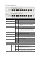
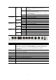
1.1 Panel Explanation LED Status Explanation ACT (Activity) Blinking Off On Blinking On The router is powered on and running normally. The router is powered off. A USB device is connected and active. The data is transmitting. The profile of CSM (Content Security Management) for IM/P2P application is enabled from Firewall >> General Setup. (Such profile is established under CSM menu). VPN tunnel is up and down. Wireless access point is ready. It will blink while wireless traffic goes through.
Right LED (Green) On Blinking LAN 1(Giga) Left LED (Green) Right LED (Green) LAN 2/3/4 Left LED (Green) Right LED (Green) WAN 2 Left LED (Green) Right LED (Green) Off On Off Blinking On Off On Off Blinking On Off On Off Blinking On Off A phone adapter with phone set has been connected (ISDN-S0) or ISDN line has been connected (ISDN-TE). ISDN-S0 (ISDN-NT) mode, it means an ISDN phone is off-hook or a phone call comes. In ISDN-TE mode, it means data, fax or voice (phone call) is transmitting.
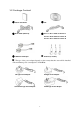
1.2 Package Content n Quick Start Guide o CD p RJ-45 Cable (Ethernet) q RJ-11 to RJ-11 Cable for Annex A RJ-45 to RJ-45 Cable for Annex B RJ-45 to RJ-11 Cable for Annex B r ISDN Phone Adapter s Antenna (n models) ^ The type of the power adapter depends on the country that the router will be installed. * The maximum power consumption is 17-23 Watt.
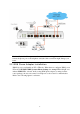
2. Installing Your Router This section will guide you to install the router through hardware connection and configure the router’s settings through web browser. 2.1 Hardware Installation Before starting to configure the router, you have to connect your devices correctly. 1. Connect the ADSL interface to the external ADSL splitter with an ADSL line cable. Also, connect Line interface to an external ADSL splitter.
Caution: Each of the Phone ports can be connected to an analog phone only. Do not connect the phone ports to the telephone wall jack. Such connection might damage your router. 2.2 ISDN Phone Adapter Installation ISDN1/2 port is configurable as NT or TE mode. When the user configures ISDN port as NT mode in IP PBX>>PBX System>>Phone Settings, the orange LED will light on to indicate ISDN-NT is selected.
Yet, if the user configures ISDN port as TE Mode in IP PBX>>PBX System>>Phone Settings, the green LED will light on to indicate ISDN-TE is selected. Then, the port is specified for ISDN line only. Refer to the following figure for reference.
2.3 Printer Installation You can install a printer onto the router for sharing printing. All the PCs connected this router can print documents via the router. The example provided here is made based on Windows XP/2000. For Windows 98/SE, please visit www.draytek.com. Before using it, please follow the steps below to configure settings for connected computers (or wireless clients). 1. Connect the printer with the router through USB/parallel port. 2. Open Start->Settings-> Printer and Faxes.
3. Open File->Add a New Computer. A welcome dialog will appear. Please click Next. 4. Click Local printer attached to this computer and click Next. 5. In this dialog, choose Create a new port Type of port and use the drop down list to select Standard TCP/IP Port. Click Next.
6. In the following dialog, type 192.168.1.1 (router’s LAN IP) in the field of Printer Name or IP Address and type IP_192.168.1.1 as the port name. Then, click Next. 7. Click Standard and choose Generic Network Card. 8. Then, in the following dialog, click Finish.
9. Now, your system will ask you to choose right name of the printer that you installed onto the router. Such step can make correct driver loaded onto your PC. When you finish the selection, click Next. 10. For the final stage, you need to go back to Control Panel-> Printers and edit the property of the new printer you have added. 11. Select "LPR" on Protocol, type p1 (number 1) as Queue Name. Then click OK. Next please refer to the red rectangle for choosing the correct protocol and UPR name.
The printer can be used for printing now. Most of the printers with different manufacturers are compatible with vigor router. Note 1: Some printers with the fax/scanning or other additional functions are not supported. If you do not know whether your printer is supported or not, please visit www.draytek.com to find out the printer list. Open Support Center->FAQ; find out the link of Printer Server FAQ; finally click the link of “What types of printers are compatible with Vigor router?”.
3. Configuring Web Pages To access Internet, please finish basic configuration after completing the hardware installation. The Quick Start Wizard is designed for you to easily set up your router for Internet access. You can directly access the Quick Start Wizard via Web Configurator. 1. Make sure your PC connects to the router correctly.
4. Enter the login password on the field of New Password and retype it on the field of Retype New Password. Then click Next to continue. 5. On the next page as shown below, please select the WAN interface (WAN 1 or WAN2) that you use. If DSL interface is used, please choose WAN1; if WAN2 interface is used, please choose WAN2. Choose Auto negotiation as the physical type for your router. Then click Next for next step.
6. On the next page as shown below, please select the appropriate Internet access type according to the information from your ISP. For example, you should select PPPoE mode if the ISP provides you PPPoE interface. Then click Next for next step. PPPoE/PPPoA: if you click PPPoE or PPPoA as the protocol, please manually enter the Username/Password provided by your ISP. Then click Next.
1483 Bridged IP /1483 Routed IP: if you choose 1483 Bridged IP / 1483 Routed IP as the protocol, you will get the following page. Please type in the IP address information originally provided by your ISP. Then click Next for next step. 7. Now you can see the following screen. It indicates that the setup is complete. Different types of connection modes will have different summary. Click Finish and then restart the router. Afterward, you will enjoy surfing on the Internet.
4. Trouble Shooting This section will guide you to solve abnormal situations if you cannot access into the Internet after installing the router and finishing the web configuration. Please follow sections below to check your basic installation status stage by stage. ¾ Checking if the hardware status is OK or not. ¾ Checking if the network connection settings on your computer are OK or not. ¾ Pinging the router from your computer. ¾ Checking if the ISP settings are OK or not.
4.2 Checking If the Network Connection Settings on Your Computer Is OK or Not Sometimes the link failure occurs due to the wrong network connection settings. After trying the above section, if the link is stilled failed, please do the steps listed below to make sure the network connection settings is OK. For Windows The example is based on Windows XP. As to the examples for other operation systems, please refer to the similar steps or find support notes in www.draytek.com. 1.
4. Select Obtain an IP address automatically and Obtain DNS server address automatically. For MacOs 1. Double click on the current used MacOs on the desktop. 2. Open the Application folder and get into Network. 3. On the Network screen, select Using DHCP from the drop down list of Configure IPv4.
4.3 Pinging the Router from Your Computer The default gateway IP address of the router is 192.168.1.1. For some reason, you might need to use “ping” command to check the link status of the router. The most important thing is that the computer will receive a reply from 192.168.1.1. If not, please check the IP address of your computer. We suggest you setting the network connection as get IP automatically. (Please refer to the section 4.2) Please follow the steps below to ping the router correctly.
4.4 Checking If the ISP Settings are OK or Not Open WAN >> Internet Access page and then check whether the ISP settings are set correctly. Click WAN1 or WAN2 link to review the settings that you configured previously. For PPPoE Users 1. Check if the Enable option is selected. 2. Check if Username and Password are entered with correct values that you got from your ISP.
For Static/Dynamic IP Users 1. Check if the Enable option is selected. 2. Check if IP address, Subnet Mask and Gateway are entered with correct values that you got from your ISP.
For MPoA Users 1. Check if the Enable option is selected. 2. Check if DSL Modem Settings is set appropriately. 3. Check if IP Address, Subnet Mask and Gateway are set correctly (must identify with the values from your ISP) if you choose Specify an IP address. For PPTP Users 1. Check if the Enable option for PPTP Link is selected.
2. Check if PPTP Server, Username, Password and WAN IP address are set correctly (must identify with the values from your ISP). 4.5 Backing to Factory Default Setting If Necessary Sometimes, a wrong connection can be improved by returning to the default settings. Try to reset the router by software or hardware. Warning: After pressing factory default setting, you will loose all settings you did before. Make sure you have recorded all useful settings before you pressing.
After restore the factory default setting, you can configure the settings for the router again to fit your personal request. 4.6 Contacting Your Dealer If the router still cannot work correctly after trying many efforts, please contact your dealer for further help right away. For any questions, please feel free to send e-mail to support@draytek.com.